Pages

Friday, January 29, 2016

Cruising Until February 9

I just picked up a last minute Cruise on the Holland America Oosterdam!
I'm leaving Friday, January 29 in Fort Lauderdale and returning on February 9, 2016.


So, no posts until I return. As I've mentioned before, Internet on the ships is ridiculously slow and expensive. I refuse to pay for it.
If I'm at a port with free Wi-Fi, I'll drop in a build post.                                                 All aboard!

I've gone ahead and posted the Quinstar steps 4 and 5.
Assembling the "cage" seems to be where some have had problems.

Estes Quinstar #7241 Build, Part 5, Dry Fit Cage


Look close at the picture to the right.
Where the outside ends cross, the holes on the outside (left of center here) should be smaller.
If you have two outside holes the same size, it is assembled incorrectly.

Try a dry fit first, no glue should be used until you are sure of the assembly.
Pieces 1 and 2 are slid together.
Enlarge the picture and you can see the numbers 1 and 2 are inside and facing each other.


Part number 3 is added.
The numbers 1, 2 and 3 are facing the inside of the structure.


Part 4 is slid in.


Part 5 finishes out the cage and forms a star and pentagon at the center.
Check the outside cross intersections. The right side will be higher than the left so the flat "K" pieces will end up at an angle.

Estes Quinstar #7241 Build, Part 4, Don't Make A Mistake! TIP


Be ready, the balsa is thin!
If it breaks, just glue back together with some CA.


Here's all the punched out girder pieces.
There are a lot of them. They are probably too small to be re-used.


Two different forum posts mention errors made when gluing together the wide center "cage" pieces. It's a complex interlocking structure and easy to get wrong.

As the instruction NOTE says:
"Numbers must face inwards toward the center of the model."
This is important. Dry fit and double check before using any glue.


Here's the numbers they are talking about.
The numbers 1 - 5 are only burned on one side of the balsa sheet.
The numbers should be at the top and all face inward when the girder "cage" is assembled.

Thursday, January 28, 2016

Estes Quinstar #7241 Build, Part 3, Balsa Prep


I usually sand off some of the burnt laser cut edges.
Don't take off too much, the fit of the parts might end up too loose.


When the center pieces are removed, there are many hold down "ticks" left along the sides.


It takes a while (there are a LOT of cut-outs) but they can be smoothed off.
Some 400 grit was wrapped around a dowel and the hold down ticks removed.


Here's an after shot showing some smoothed cut-outs.

Wednesday, January 27, 2016

Estes Quinstar #7241 Build, Part 2, Balsa Prep

The instructions have you make the engine mount first.
I'm going to wait as there will be some changes to adapt it for both 18mm and 24mm flights.

I'm not going to fill all the balsa, that could make an already draggy model too heavy. I decided to fill just the flat surfaces you will see looking down from the top.


The balsa sheet is 1/16" thick. CWF was brushed on while the perimeter pieces were still attached to the sheet.
Notice the number "3" on the center of the large center piece. I only brushed filler onto one side of the sheet, the side with the numbers on them. These will end up being the top side of the horizontal pieces.

The instructions have you sand the pieces while still attached to the sheets.
TIP: Sand up and down, not side to side as shown in the instructions. If you sand side to side you'll hit the vertical slots. Look at the top picture, you can see they are lifting.


Here I'm sanding up and down with 400 grit.
Sand enough to smooth the balsa, you don't want to thin it any more than it is.

Tuesday, January 26, 2016

Estes Quinstar #7241 Build, Part 1, Parts

This should be fun!
Here's another kit that shows what can be accomplished using laser cut balsa.
"Quin" is named for the five point star saucer. No nose cone on this one, it's much larger than the Blenders.
Blenders use 13mm engines, the Quinstar is made for 18mm engines, the B6-0 and C6-0. The C6-0 altitude is only 150 feet.
I just might convert it for 24mm engines. It should be strong enough, the 1/16" balsa is well supported with all the interlocking struts.

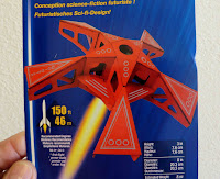
The face card is actually a picture of a finished model, not redrawn or smoothed out using photo editing. You can see balsa grain pores. The horizontal flat piece "M" has the hole for the launch lug. There is no lug in the face card picture.


Parts of interest: 
There are five laser cut sheets of 1/16" thick balsa.
A small sheet of silver decals.
A standard 20/50 engine mount with Mylar retaining ring.


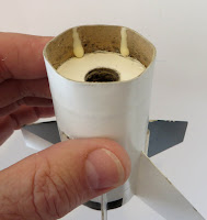
The BT-50 tube was flattened a bit. Not creased, but flattened.
This was like some tubing found in the STM 012 kit. The kit bag isn't big enough and compresses down on the tubes.

Q2G2 Cluster Ignition Questions?

On TRF, "ActingLikeAKid" asked why the Estes Pro Series Igniters were called "Sonic".

Later in the thread, "Samb" posted a video link to the NARAM 56 Manufacturer's Forum. This was recorded a year and a half back.
Bill Stine talked about Q2G2 igniter availability. His explanation tells why they became scarce. I've seen this video before, but it has been a while.
To see the video, CLICK HERE , go to about 40 minutes in.


Mr. Stine talked a new "pyrogen" formulation. The igniters sold separately from the engines (as accesories) will have "A slightly slower response time."
Maybe this is what led to some cluster ignition problems mentioned in Daniel Petrie's blog post? CLICK HERE
I'm curious if others have had cluster ignition problems using a newer Q2G2 "pyrogen" tip.

From my end, this is speculation. All my Q2G2 igniters are older and still work fine in clusters.
I would be wary about using the clear tip Estes "Starters" in cluster ignitions.

Monday, January 25, 2016

Estes Little Joe II Kit Observations

It's going to be a bit before I assemble the new Estes Little Joe. I know there'll be plenty of build threads, JeffyJeep has already started his on TRF.

Two things I did notice opening the box -
When I picked up the kit box, things were sliding around inside. You could hear the body tube hitting the box ends. There is some extra room inside.


The plastic parts bags are different.
The Centuri capsule parts bag says "Made in the U.S.A."
The new raceway parts bag is from China.
The fins and nozzle pieces aren't marked with their origin.


I had hoped the parachute would be the 24" Saturn V style like in the Saturn V kit reissue.
This one is the standard (newer) Estes checkerboard. I'll give the shroud lines a test "tug" later on.

New Estes Mercury Redstone Kit Run


I had heard that Estes corrected the decals on the Mercury Redstone kit. I saw the new kit run yesterday at Hobby Lobby.

The face card is now a black background, much like the Saturn V (#2157) and new Little Joe II.
The vertical UNITED STATES decal looks to be a darker red, the plastic capsule and tower parts still look pink to me.


The "MR8" is a correction builders are looking for. You can see it above the fins.
MR8 designates the Liberty Bell 7 flight.

Thanks to Estes for listening and making the corrections.

Sunday, January 24, 2016

The BIG FIX, Alway Saturn IV, Part 2


When exposed to the elements, you can see how the BT-5 tubes re-shaped the BT-60 lower fin can tube.
Wood glue was dripped down the sides where the tube cluster would make contact.
More glue was added to the bottoms of the BT-5 tubes before it was slid together.


Good thing I remembered there were two launch lugs!
A launch rod was slid between the upper and lower sections to insure all was lined up.


Here's the rebuilt model.
I didn't re-install an engine hook. The tube extends out the back enough for a tape wrap extension.

Replacement decals were printed but I haven't decided if they will be added. I probably won't add all the nose cone details.

Sometimes a rebuild requires re-finishing to look brand new.
Sometimes a rebuilt model has deserved its scars.

Saturday, January 23, 2016

The BIG FIX, Alway Saturn IV, Part 1


My Alway Saturn IV sat in a tree for a month after a B6-4 flight last May.
At the June club launch I found it at the base of a tree. It was wet and the soaked body tubes were squishy.
CLICK HERE to see the story.
I let it dry out. While the tubes are showing their seams now, the model feels very strong. There are six BT-5 tubes at the bottom. The paint and vinyl Contact paper trim was clean. The home print decals were starting to release.
Well constructed and sealed models stay together longer. If this were a "naked" build, there wouldn't be anything left after the rain and sun exposure.
I finally got around to gluing it back together.


Lonnie B. knew I needed a new nosecone. The original nose cone and parachute were still high up in the tree.
Lonnie donated a Bullpup kit, the right nosecone is in the kit bag.

Problem was, the BT-55 body tube had shrunk!
I sanded the shoulder until I got a good slip fit. I was concerned, too much sanding and I would have gone through the plastic wall!


I never liked the shock cord attachment on this nose cone.
The plastic loop was cut off and the hole at the base was widened.

A shock cord was tied through the base and one of the loop holes.


I don't use masking tape to hold engine hooks on the engine mount tube. They do decompose over time.

The old engine mount tube was pulled out, the electrical tape had to be removed afterwards. The tape still looked new and the overlap was still strongly adhered.

Friday, January 22, 2016

The BIG FIX, Quest Magnum Engine Mount


Here's the carnage after my Quest Magnum launch a few months back.
On the far left you can see the two engine cluster mount, still tethered by the Kevlar line.
Moving to the right is the Quest kit parachute, a clean break, torn in half! Five of the six shroud lines were still attached.
The fins and body tube are fine. This model is my favorite Quest kit, well worth repairing.


The parachute is an easy replacement. The engine mount took a little more work.
At the top you can see some black from the ejection charge blowing back through the ends of the crescent centering rings.
The Kevlar line is dirty, but still very strong.


I have a few marked sticks to apply a line of glue for the forward centering rings.
Glue drops are applied to the end and the stick turned inside the body tube until I get a fair sized bead. Not too much glue, you don't want the glue to shrink and "Coke bottle" the body tube.
Some instructions have you apply glue and slide the mount into place.
Here I slid in the mount but not far enough to hit the glue bead already in place.
More glue was applied around the end for the lower ring contact.

When I can (if the glue isn't setting up too quickly) I turn the mount right before it is in its final position. This spreads out the glue bead evenly for an internal fillet.

Thursday, January 21, 2016

Little Joe II Unboxing

On TRF, George Gassaway posted a link to the Little Joe II "un-boxing". James Duffy (RocketAero.com) opens the box and narrates. To see the video, CLICK HERE
At 11:20 the large water slide roll pattern decal is shown. This is a big decal wrap and might be  difficult to apply. Mr. Duffy remarks he will mask and paint the roll pattern instead of using the decal. Many builder's had trouble with the large Pro Series II Red Max decal wrap. Maybe this decal can be cut into smaller pieces and applied?
On TRF, even John Boren commented: "By far the hardest part of building this model is getting the large black decals in place on the main body. I might even mask the upper body tube off so I can paint these areas in Black since I simply HATE applying decals. 
The vertical UNITED STATES goes onto and into the corrugated wrap. Some Micro-Sol Setting Solution might be needed to get the decal to lay into the ridges.

JeffyJeep is already doing a build on YORF, CLICK HERE

New Way A-20 Demon Build Part 16, Decals and Finished


The instructions said this upper Demon wrap is the most difficult to apply but I didn't have any problems.

The New Way instructions said to place it 1/2" down from the top of the tube. The old Estes catalog pictures showed it about 1/8" from the top. The 1/8" spacing looked too tight for me. I compromised at a 1/4" spacing.


The finished square Demon looks great! 
The New Way square tubing does need some extra filling and smooth sanding. This was a fun build and an escape from the ordinary
The face card says it uses a D12-3 engine. My build weighs in at about 4 oz.
I would think a D12-5 is a better fit.


I'm looking forward to flying this one.
LAUNCH UPDATE: From the January 9 NEFAR Launch, scroll down to the bottom:
CLICK HERE

Wednesday, January 20, 2016

New Way A-20 Demon Build Part 15, Fin Plates


The fin plates are also cut out. There are eight, one goes on each side of a fin tucked into a fillet.

Leave the backing on the pieces. Crease the center line over the side of a straightedge.

The pieces are shown folded in the inset picture.
The top of the plates are set 1/2" from the tip of the leading edge.

I cut a business card to the angle of the leading edge. It is marked 1/2" down from the leading edge tip.

The right side of the four fins were pencil marked at the 1/2" mark. You only have to mark the right side of the fin.


Set the plated into the crux of the fin joints using the tip of your knife.


Don't burnish until you are sure the crease is centered and into the fillet.
Set down just the four right sides for now.


Look onto and over the leading edge to line up the left side plates.

Tuesday, January 19, 2016

New Way A-20 Demon Build Part 14, More Chrome Trim


I checked the width of the low wrap around the upper part of the body tube. It's easier to mark the edge cuts without the trailing edge of fins in the way.
I tried to trim the ends so the butted seam would be centered between the series of doubled row dots.


The "zig-zag" line is first centered on the body tube corner.


The applied low body wrap.