Some posts may show assemblies on a naked test flight model, other steps might show details from a non-flying display model.
Thursday, June 16, 2022
Odd'l Rockets F-18 Hornet Development & Build, Part 2, Parts
This build will be a little different.
I'll be going back and forth between the first prototype (rough build), then show changes made before the kit was bagged up and released.
Wednesday, June 15, 2022
Odd'l Rockets F-18 Hornet Development & Build, Part 1, Background
Centuri introduced three Fighter Fleet kits in their second 1976 catalog.
The F-4 Phantom, F-15 Eagle and F-16 Fighter.
I go through a LOT of photos.
To see them: CLICK HERE
I had already produced the Odd'l Rockets F-16 and F-104 Starfighter kits. I wanted to make them closer to the lines of the real jets and keep them stable.
There are compromises when designing a stable sport rendition of a Fighter Jet.
My goal was to make a good representation using existing tubes, nose cones and balsa.
If I'm lucky, I'll come across an accurate line drawing like this one shown on the left.
Portions of this drawing was enlarged, wing and stabilizer shapes were directly traced.
If you see the Centuri F-104 Starfighter model side by side with the Odd'l version you would see some differences. The Odd'l Fighter Jets are designed to look more accurate. These new kits are more of a build challenge.
I would have loved to do the Blue Angels version, but licensing fees would set the kit price out of reach.
Test model development and the kit build start tomorrow.
Tuesday, June 14, 2022
Original Estes Mars Snooper
The kit was first
available in 1965.
Launch it with a 1/2A engine? I don't think so -
Inspiration for the design first appeared in an ad advertisement for American Bosch Arma Corporation, 1959. Art by Frank Tinsley.
"Mars Snooper. Mars can be seen in the background as a reconnaissance craft prepares to land on the surface of red planet's moon, Deimos."
The Snooper kit design goes back to 1964.
It was originally a Estes "Rocket Plan #25.
To see the plans, CLICK HERE
Check out the fin pods, back then made by shaping balsa.
The three part shroud assembly is different, the low shroud is shorter in length.
The smaller upper fins have changed over the years - sometimes rounded off, other times with squared corners.
Monday, June 13, 2022
New Way Boxie Birdie, Build Part 7, Decals & Finished
The decals are placed and the build is complete.
Sunday, June 12, 2022
New Way Boxie Birdie, Build Part 6, White Paint, Red Trim
In the pictures below you can see the masking tape placed on the inside surfaces.
The birdie is painted gloss white and allowed to dry.
Lightly set the top red vinyl trim in place.
Check underneath from all four sides to be sure it is centered before pressing down in place.
Roll over the sides of the top vinyl piece and burnish into place.
The long rectangle red piece is started directly at the center line of the launch lug. This hides the seam when the rocket is slid down the launch rod.
Saturday, June 11, 2022
New Way Boxie Birdie, Build Part 5, Assembly
Apply a line of glue around the inside edge and press in place.
Check to be sure it is level and even before the glue sets up.
The engine mount tube gets a line of glue inside the end to slip around the engine block already in place.
Slide in and over the engine block.
Some glue will be pushed up inside the tube at the bottom of the engine block.
TIP: It's a good idea to remove as much of the glue as you can. I used a long Q-tip to remove the excess glue.
It's probably not a concern with this rocket as the engine is ejected. But on other models, a hot engine could melt glue on the inside of the engine mount tube making it hard to remove.
The cap is in place -
The square launch lug is glued into the rectangular hole and through the centering square inside. The top is even with the low edge of the cap assembly.
Friday, June 10, 2022
New Way Boxie Birdie, Build Part 4, Gluing Together The Body
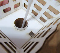
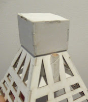
the cage was held together with the cap slid in place - no glue.
You can see the engine block inside the top.
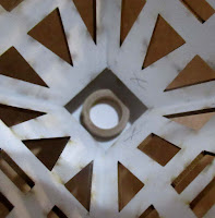
I set the rear centering square in place and leveled it as best I could.
The corners were marked with a pencil.
Small bits of glue were set at the pencil marks.
The plate was pressed into the glue dots and leveled.
Subscribe to:
Posts (Atom)