Showing posts with label Engine Block. Show all posts

Wednesday, February 19, 2025

Estes Star Seeker (Tri-Pack) Kit #0866, Part 4, Engine Block & Kevlar ShockCord


The original kit had two engine blocks,
one for the engine stop, the second to tie a rubber shock cord. No parachute or streamer, just nose-blow recovery.
Enlarge the picture on the left.

I can't imagine trying to slide in that upper block ring into a ring of glue with a binding rubber shock cord tied around it.

I'll be installing a single lower engine block with a tied on Kevlar line.


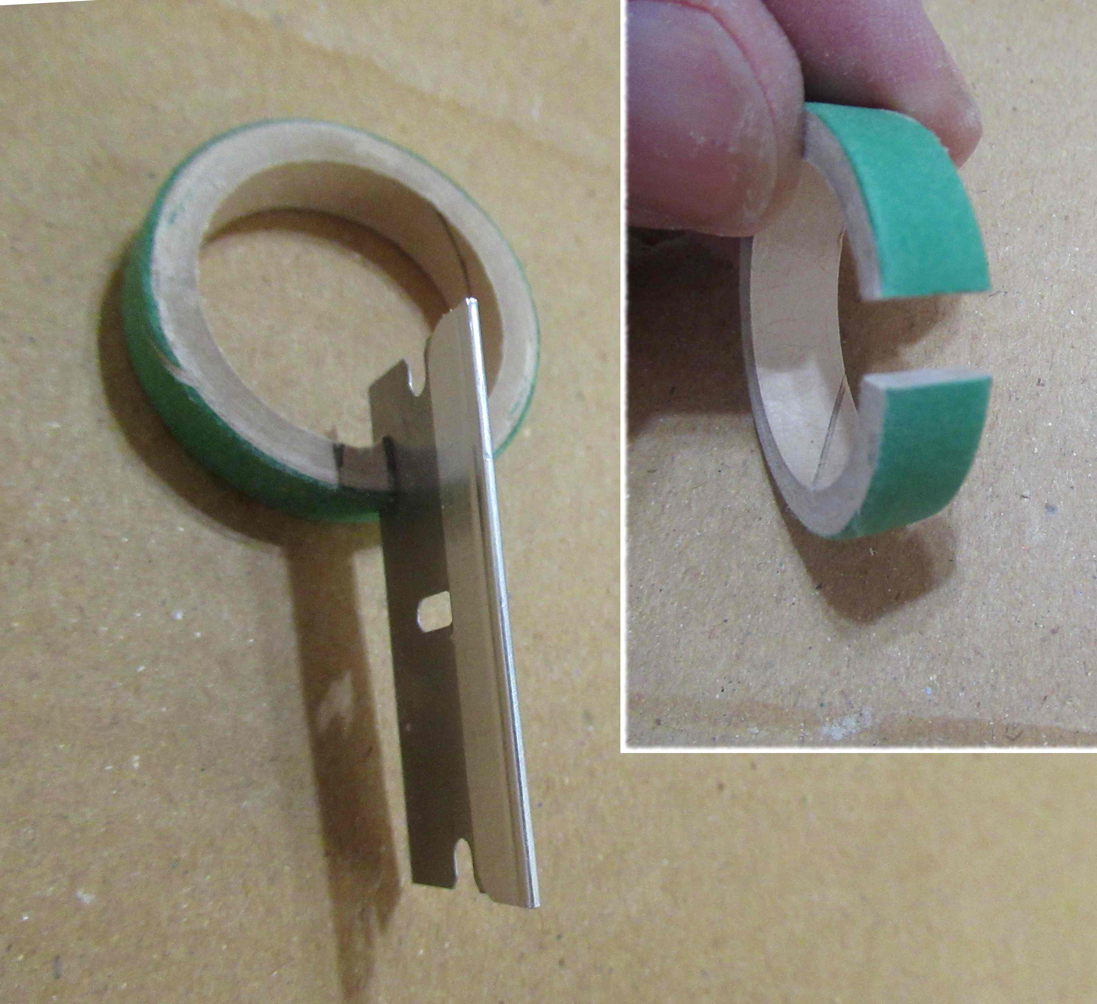
The engine block got a notch for a better fit of the Kevlar line tie.


The inside 1/8" (or so) of the tube got a wipe of CA glue. This was followed by sanding just the edge with 400 grit on a block.


I used a spent "T" motor to position the engine block and Kevlar line.

Occasionally your find a raised cut-off burr on the end of the casing. Roll that off with some 400 grit.
This makes for an easier slide into the engine mount tube.


TIP: When installing an engine block, have ALL your parts close at hand. You don't want to be looking for the engine block as the glue in the tube is starting to set.

The glue applying dowel is marked with a pencil ring about 1 1/2" from the top. 
A ring of glue is set around the top of the dowel.
Set the dowel in the tube up to the pencil line trying not to touch the inside walls of the tube. 
Roll the dowel and transfer a line of glue around the inside of the tube.

Quickly set in the engine block and push into position, with 1/4" of the engine casing extended out the bottom of the tube. Remove the casing.

Tuesday, April 9, 2024

Estes Mini Bertha Clone, #TK-3, Part 4, Slightly Longer Engine Mount?


An engine block wasn't included in the original kit.
I added one, glued in so it's flush with the upper centering ring and body tube edge.
Here's why that engine hook was designed to hang 1/2" beyond the bottom of the mount!
There isn't much clearance and flex between the BT-5 and BT-20 tubes. The low bend of the engine hook scrapes along the outside of of an engine casing when slid into the mount.

It's not impossible to get the engine in the mount, you'll just have some friction when being slid into place.

I pressed the mount into place with the flat face of my sanding block. The Kevlar was fed out the back and layed to the side while pressing the mount into the tube.

The mount is certainly useable with the shorter overhang hook. 
TIP: This is a BMS 1 3/4" engine hook. The cut off ends were a little rough. I smoothed out the edges with a few passes of a small, flat diamond file. The engine slides in easier now.

With the Bertha's fin trailing edges in the way it takes a moment to work an mini engine into the mount.
I'm sticking with the modification I made.

Monday, October 31, 2022

Estes Odyssey #7235 Build, Part 9, Engine Mount


One of the 50/55 centering rings will need to be notched to allow engine hook flex.

I usually cut the notch with a single edge razor blade. You can simply press down on the blade and get a clean cut.
Notice the angle of the set blade. When cutting at this angle you can end up with sides that match the movement travel of the engine hook. 


Set the glued notched ring into the BT-55 body to hold the ends down as the glue dries.

I did cut off the finger tab . . . because I'm a big boy.


A sparse line of glue is rolled around the tube and the black retainer ring is slid into and over the glue until it rests against the top of the lower centering ring.
Fillets are then added.

The engine block ends up recessed inside the top of the mount when slid in against the top bend of the engine hook.

Monday, September 5, 2022

ASP Micro Sandia Sandhawk Build, Part 4, Engine Mount


The engine block is a little different on this one.
You have two 1 1/2" long couplers included in the kit.

To make the engine block, one coupler is cut in two making a 3/4" long block. It is easiest to use a single edge razor blade for this cut.

The Kevlar line is looped and tied around the coupler and tied.

Mark the second coupler at 3/4". This depth gauge allows a MMX motor to extend 1/4" out the back of the body. 

Thread the Kevlar line through the tube and out the top. Slide the 3/4" long coupler block into the tube end. 
Push the engine block into the tube up to the 3/4" pencil mark on the longer coupler.


The instructions say to use Super Glue (CA) to set the coupler/block.
I used a small drop of wood glue set in place with a Q-tip stick. 
 

Monday, March 14, 2022

Estes Delta Wedge Clone #1931 Build, Part 6, Lug Fillets & Engine Block


After the glue dried, This shows how little was used in the rear plate fillets.

No glue on the lugs yet.


I ran a line of glue down one side of the lug.

The lug is turned from the back pushing the glue line into the joint.
Now you can add some glue to the back end of the lug/plate joints.
I didn't like that there was no engine block. I'd rather use some Kevlar tied to the block than have a tri-fold shock cord mount blocking the parachute.

A notch was cut in the block and Kevlar tied on.
The block will be slid down from the top of the tube dry, and meet the glue line applied in the next picture. 
For now, position the block in a "ready" position to be slid down using a dowel.

Using a dowel, a line of glue was set in the tube just above the upper bend of the engine hook.

The block was pushed into the glue, down from the top using a dowel. Keep sliding the block down until it rests against the upper bend of the hook.

Remove any excess glue using two Q-tips taped together for the extra length needed to reach it.

Friday, November 19, 2021

Rocketship Games MMX Hawkeye, Part 6, Engine Block & Fin Gluing


I made a "Block and Tackle" (Jim Flis idea) to set the engine block in the body tube. 
A simple 1/8" wide wrap of tape stops the engine casing when pressing the engine block in place. This will leave a friction fitted MMX engine with 1/8" extended out the back of the tube.
Here's the toothpick included in the kit.
I measured just below the engine block position so it would hit the glue before ending up in it's location.
The Kevlar line is tied to the loop at the top of the red engine block.

Mark the toothpick with pencil,
A drop of glue is applied to the top of the toothpick and set in the tube using the pencil line as a depth gauge.
The block is slipped in and pressed into place with the taped engine casing.


The wings and rudder fins are glued onto the laser cut lines on the body tube.

The forward small vane fins are glued to the lines towards the front of the tube.

Dry fit the Dorsal Bar piece before applying any glue. You may have to widen the slot to slide over the Rudder fin.
The Dorsal Bar piece is glued over the top rudder fin.

Mine overhang the back by about 1/16". That will be trimmed off after the glue dries.

Thursday, November 18, 2021

Rocketship Games MMX Hawkeye, Part 5, Filler/Primer Sand & Kevlar Tie


This shows the before and after sanding of the filler/primer shot coats. You can easily see the gray filler/primer left in the grain pores when it is sanded to surface.
The CWF filler fills 3/4 of the balsa.
The filler/primer fills any remaining grain.
A simpler two-step process than the old four coat sanding sealer fill.

Here I've sanded the filler/primer off most of the upper end of the main tube. After sanding, the laser cut fin positioning lines were still visible and useable.
This is the 3D printed combination engine block and Kevlar tie point.
This piece has ridges, like most of the 3D printed parts I've seen. The nose cone was much smoother. The ridges won't matter, the engine block won't be seen inside the body tube.

As suggested in the instructions, I applied some glue to the end of the Kevlar to keep it from unraveling.

Tuesday, July 20, 2021

Piglet-sus! Build Part 5 Engine Mount


Here's both rolled centering rings on either side of the motor mount tube.
I did use a sanding block to smooth out the flat sides of the rolled rings.  Be sure the glue is dry before sanding flat.


A small hole is drilled for the Kevlar shock cord.
Look close at the picture and you can see the gray engine block glued flush with the forward end of the mount.
1/8" was cut from an expended MMX engine casing to make the block.


Two overhand knots were tied on one end of the Kevlar shock cord. The free end was fed through the drilled hole.
The knot was pulled tight against the centering ring and glued down.

Tuesday, June 15, 2021

Estes Indicator #7244 Build, Part 2, Some Parts Prepping


The fins show clean laser cutting but some of the line segments didn't match up.
These should be squared up with a block or you won't have a good root edge bond. 


Here's what I mean - 

This shows the edge sanding about halfway through the sanding. Keep sanding until the burnt edge is nearly gone.


I also like to square up and flatten the engine block and those thick 20/50 centering rings.

A squared up engine block can fit better against the upper bend of an engine hook. 
Sometimes a low engine mount centering ring is set flush with the end of the main airframe tube. Square it up and the joint will be less noticeable on the finished model. 

The finger tab was cut off because I'm a big boy.

Flip over the hook and put the cut end at the top of the mount.

The inset picture shows the bent end of the mount after hitting it with a metal file to roll off the sharp corners. This makes engine insertion easier.

Sunday, May 30, 2021

FlisKits Space Raider Build, Part 3, Engine Block & Fins

This model has a standard minimum diameter engine mount.
Kevlar is tied around a notched engine block.
Glue is applied inside. The block is slid into position with an empty engine casing until 1/4" of the casing extends out the back.
The Jim Flis instructions say to use 1/8" thick balsa for the fins. That looks like it would match the fin thickness in the original black and white photograph. I didn't have any 1/8" so I went with 3/32" thick.

I figured with the printed covers the fin thickness would end up close to a 1/8" thickness. In the end, the 3/32" balsa and fin covers fit the slots in the body shroud very well.

You'll go through a lot of balsa on this one!

Tuesday, April 27, 2021

ASP Micro Hawk Build, Part 2, Engine Block & Kevlar Tie

You are supplied with two brown couplers.
Mark one coupler at 1/4". With a sharp knife, cut off the 1/4" end to be used as an engine block.

I like to restore the round shape and press down any burrs by rotating the block on a sharpened dowel.

The Kevlar line is tied on the engine block. Pull the knot to the top side of the block so the tied bulge won't contact the inside of the body tube.

The coupler is marked at 3/4" for a depth gauge. 
Note the top of the coupler was rounded off with 400 grit for easier insertion.
Slide the block into the long tube, no glue yet. Push into position using the long coupler up to the 3/4" pencil mark.

The inset picture shows a small amount of glue on the tip of a Q-tip. Insert in the back without touching the inside of the tube. Wipe off the glue at the engine block / tube joint.

The picture looks like I'm holding a Camel cigarette.

Tuesday, March 2, 2021

ASP MMX Jayhawk Build, Part 6, Shock Cord & Engine Block


The supplied Kevlar shock cord is longer than you'll need.
I got a better idea of the length slipping the loose end through the body tube, letting it hang out the back. 

1/4" of coupler is cut off and used for the engine block. 
Tie the Kevlar onto the engine block.

Mark a length of remaining coupler at 3/4" to use for the engine block placement. Glue the engine block into place.


The small launch lugs are glue in line.


The nose cone was glued in place with Fabri-Tac.
As it was setting up, it slid up, leaving a small gap at the shoulder lip.

I filled the gap with CWF followed with a shot of filler/primer. After sanding it down the gap was pretty much gone.

Tuesday, February 16, 2021

Estes Airborne Surveillance Missile Build, #0867, Part 5, Engine Mount


Usually the instructions have you glue on the rings and blocks to one side of the pencil marks. This kit has you set the rings on either sides of the marks.

The smaller middle ring is very close to the dowel notched ring. 
Set a line of glue around the tube and slide the notched ring into the glue. Smooth out the fillet using a Q-tip. You'd never be able to get a fingertip in there.
Here's the finished engine mount - 
Be sure the small notches in the dowel notch ring are directly over the fin position lines already drawn on the tube.
TIP: This is not my idea, but it's a good one - Fliskits used to sell an accessory called the "Block and Tackle". 

The 1/4" wraps of  masking tape at the low end of the spacer tube work as a depth "stop" preventing the engine block from ending up too high up inside the tube.
Place a line of glue high up in the tube. Slip in the engine block. Slide the spacer tube in the tube pushing the engine block up. Keep sliding in the engine block until the spacer tube stops when it hits the tape ring at the bottom of the BT-5 tube. Remove the spacer tube. 
On the right side, the tape wrapped spacer tube is almost butted up against the bottom of the BT-5 tube.

Keep the taped spacer tube for future use. Make up and use BT-20 and BT-50 "Block & Tackle" tools as needed. Most rockets have the engine extend 1/4" out the back of the engine mount tube.

Sunday, January 31, 2021

Estes Twin Factor #7250, Build, Part 9, Engine Blocks & Launch Lugs

The instructions show the two yellow spacing tubes taped together. They are pictured pushing the lower engine block in place.

I simply glued the lower engine block in the bottom, even with the end of the BT-5 tube without using the yellow tubes..
With the lower engine block glued into the bottom of the booster stage - 
Slide in the two taped together yellow spacer tubes into the booster stage. Slide the upper stage body down on the top half of the taped yellow tubes. 

The upper engine block is slid down from the top until it butts up against the yellow spacer tube. I applied a glue fillet around the top joint.


Here's one of the short launch lugs glued into the root edge fin joint.
Both the top and bottom lugs are glued towards the top leading edge of the adjacent fin.
Here's a step that isn't really needed, but I did it anyway hoping for a smoother final finish.

Some CWF filler was directed into the joint seams with the tip of a dull knife blade. After it dried, the bottom was sanded with 400 grit.
One shot of filler/primer and sanding followed, filling any remaining seams.

Tuesday, October 20, 2020

Estes Starliner #0863 Build, Part 3, Engine Mount


The upper ring is slotted for the Kevlar line to pass under.

The original instructions have you use a tri-fold mount, but I find them too thick on BT-5 and BT-20 based models. A Kevlar line tied to the engine mount won't block the ejection of the parachute.

Note the wrap of electrical tape, the pictures are out of order - this engine hook retention is explained below.


This is the top of the mount.
The kit didn't include an engine block, I feel better about the mount with a block inside.

A glue ring was set in using a Q-tip.
An expended engine was used to push the engine block squarely into the tube. Sometimes an engine block can go in crooked when it hits one side of  the engine hook.


There was no engine hook retention ring in the original kit. The engine hook doesn't sit flat against the tube.

I added a wrap of electrical tape to hold it down.


Here's the finished mount with the three upgrades - Kevlar, engine block and hook retention.