Showing posts with label E Indicator. Show all posts

Friday, June 25, 2021

Estes Indicator #7244 Build, Finished


Even with my painting error and decal problems, the model looks good.

It's size reminds me of the Estes kits from the late 1960s.


The mid section is clean.

Starting a decal wrap at the back hides the mis-match of the checker
pattern.


There you go - 
Another good 13mm rocket for the smaller soccer field.

Thursday, June 24, 2021

Estes Indicator #7244 Build, Part 11, Decals - Ack!

I took a good look at the decal sheet and realized my dilemma. There were decals for two black fins and one red fin. I decided to leave some on and others off. I usually plan ahead and should have seen this coming.
 
I checked the roll wrap decal with a dry fit at the top of the BT-50 tube section.
I hate it when this happens! The decal wrap hits the short upper launch lug. 

One way around this is to cut the decal and make a flap that will be cut off later after it dries.

On the left, the cut slit allows the decal to sit underneath the launch lug. The upper red stripe is actually going around the top of the lug.

The checker pattern didn't match up! Another reason why I hide the decal meeting point on the back/launch lug side of the model. I did my best to trim the overhang but the thin decal didn't cooperate.

These were very thin decals and probably could have used a acrylic clear coat to thicken them up before soaking.  But - kit supplied decals shouldn't require that from the builder.
Two decals tore when sliding off the backing paper. Other decals wanted to fold under and needed careful transfers.

Wednesday, June 23, 2021

Estes Indicator #7244 Build, Part 10, Black Fin & Shock Cord Tie

Here's the mask for the lower black fin. An upper fin also got black paint
As shown before, I use Scotch tape for masking. I mark the clear tape  with a wide Sharpie pen before cutting the strip.

The Sharpie ink can transfer to your fingers and onto the model. Instead of smoothing down and sealing the tape edge with a fingernail, I use a Q-tip. You can see a bit of black ink left on the Q-tip.


Here's the low black fin after shooting with paint.


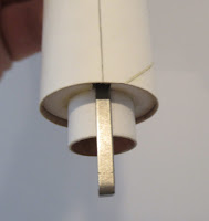
I usually leave a short tail on the shock cord tie.
This tail is tucked into the open slot below tie down loop. This keeps the loose end of the cord from getting stuck between the adapter shoulder and body tube.


The rocket looks good before the decals were added. 
I could have left it like this . . .

Tuesday, June 22, 2021

Estes Indicator #7244 Build, Part 9, Red Fins

Well, I messed up! 
I should have paid closer attention to the face card coloring. It's not immediately apparent, but there are two black fins and one red fin. I got those reversed. You've really got to look close to find that second black fin. Not a big deal, but that won't work with the supplied decals! I didn't notice until I went to apply the decals.


The rounded leading edges of the fins needed a little push with a knife blade to make the curve smoother.


It looks pretty good - so far!


Most of the straight root edge masks were good -

This one was a bit rough. Oh well!


The low end of the upper fins root edges look okay.
As I mentioned earlier, there is little chance of the low end making contact on landing or breaking off.

Monday, June 21, 2021

Estes Indicator #7244 Build, Part 8, White Undercoat & Kevlar Mount


I only did glue fillets where the root edges contact the body tube.
No wood glue will go on the adapter area. There is little chance of the low end of the fin making any contact with the ground or breaking off.

TIP: When applying glue for a fillet - (left side picture)
Squeeze the bottle to start the fillet, then stop squeezing and simply let the glue flow as you draw the nozzle down the root edge.

The right side picture shows the same glue line smoothed out.


The entire model got hit with it's first gloss white undercoat.

Light sanding follows with some 400 grit. The outside of the glue fillets are usually rough and will need some smoothing.

A second white undercoat followed, with even lighter sanding with an older piece of 400 grit.

Notice the reflection on the flat side of the fin. I was just knocking down the tops of  the slight orange peel.

I should have tied some Kevlar to the engine mount, but this engine mount had thinner cardstock rings.

The lower body tube section is a BT-50. 
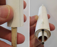
Some Kevlar was tied around a notched 20/50 centering ring.
This was pressed into place using the base of the 20/50 plastic adapter.
A glue fillet was applied around the top joint of the ring.

Sunday, June 20, 2021

Estes Indicator #7244 Build, Part 7, Fin Primer & Fin Gluing


The fins were held down to scrap cardboard, set on tape with the sticky side up.


Before spraying with filler/primer,
The balsa fins got swept over with a wide brush.

This removes any dust after the CWF sanding without using a tack cloth. A newer tack cloth can leave a sticky surface. 


Here's a before and after sanding down the filler/primer to surface with 400 grit. You can see some gray filler left in the body tube wrap seams.

Note the primer is removed at the penciled fin line. Sand just enough to rough up the tube, no need to remove the glassine wrap.
I didn't glue the adapter into the upper tube yet. I thought it would be easier to mask and paint the fins without the adapter in the way. The adapter will be glued in after the two different colors are shot.

The root edge fit against the adapter is pretty tight. It should make a clean color separation after painting.

Saturday, June 19, 2021

Estes Indicator #7244 Build, Part 6, Engine Mount Gluing & Adapter Fill


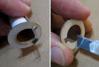
The instructions imply that the rear centering ring is even with the low edge of the body tube.
The picture shows a dry fit, no glue yet.
If you recess the lower ring about 1/16", you can add a glue fillet along the bottom joint.

I like to use a dowel to apply the inside ring of glue for the upper centering ring on the mount.

Set the dowel next to the mount and mark just below the lower ring. With the glue bead (in the tube) slightly below its final position, you will push the glue up creating an interior fillet.
Don't use too much glue - the tube could shrink in as it dries leaving a "Coke Bottle" ring depression.

On the left I'm rolling the glued dowel around the inside of the tube using the pencil mark as a depth gauge.

Turn the mount as you slide it into the glue ring, making a more even interior fillet.
The engine hook is in line with the two launch lugs.
There is two small dents where the adapter was twisted off the mold tree.

I fill them with a dot of medium CA glue. A drop of CA will take a few minutes to dry before sanding to surface.

Note the adapter is slid out a little so it won't be glued into the tube yet.

Friday, June 18, 2021

Estes Indicator #7244 Build, Part 5, Truing Up Fins & Balsa Fill


The outside edges of the the upper fins will need to be evened up with a block.
When gluing up the two piece fins, I was more concerned with the root edge fit against the body tube and adapter. With those edges held against the body tube and adapter - the outside edges weren't in line.
On the lower fins - 
I rounded the leading edge of the smaller strake piece before gluing the pieces together.
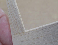
I find it easier to "feather-in" the other leading edge (inside corner) to the rounded strake after it is joined. 

Notice the angle of the sanding block. At this 45 degree angle you can sand in a 45 degree "pocket" into the corner.


Here's a pretty good example of the inside corner of the leading edges.


Most new builders freak out when the CWF filler dries, especially on thin balsa like this. Water based filler does warp the wood when only one side is painted and dries.
Don't panic - when the other side gets a coat of CWF, the wood will straighten out.

Years back - When sanding sealer dried it would warp balsa, but not to this extent. 


When sanding off and smoothing the dried CWF,
Hold the fin under a bright light and check the shadows. Here towards the small tip, you can still see a brush stroke. This will need a little more sanding to bring that filler down to the surface.

Thursday, June 17, 2021

Estes Indicator #7244 Build, Part 4, Fins & Adapter


Here's how the two piece fins will glue up.

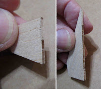
There are six fins total, two pieces per fin.

Glue these up against a straightedge. I like to set some small weights on the glue joint seam so both pieces end up flat.


The upper fin root edge is glued to the body tube - 
The root edge on the low fin is angled to fit the 20/50 adapter. 


Speaking of the adapter - There is a tie down loop on the top.
I would think this might stop the ejection charge. Except for an open rectangle space under the tie loop, this seems like a blockage.

This question came up on a forum. Estes replied that it doesn't impede the ejection charge or deployment of the parachute.


I cut the end off using a razor saw. 

Here's the new open top end after rounding off the rough sawn edge.

Wednesday, June 16, 2021

Estes Indicator #7244 Build, Part 3, More Parts Prepping

Square up the tubes by sanding the ends with 220 grit. You might be surprised by how many kit tubes aren't cut clean.

Pick an end and mark the BT-20 body tube Front and Rear.

You can do a wipe of CA glue on the top (nose cone) end of the BT-20 tube only - All other tube ends will have glue applied later. The CA glue edge would seal the tubes - wood or plastic glue won't soak in.


This is the 13mm engine mount tube.
At the top is the slit for the engine hook.

Notice there are more than one mark going around the tube at the centering ring and Mylar retaining ring locations. I like making three or four marks so I know the rings are perpendicular to the tube.

The fit of the flat 5/50 centering rings were too tight on the BT-5 engine mount tube.

I did some simple scraping to open up the inside diameter.
Uh-Oh!
I've never checked the shroud line length on a premade parachute.
The two adjoining chute "corners" were matched up and the center area of the shroud line loop stretched tight. 
Each shroud line loop was a different length, two are shown here. This could make for a lopsided parachute. 
I cut off the shroud lines and replaced them with #10 embroidery thread.

I know - the parachute would work fine as is, right out of the kit bag.
I'm single and have time for very important rocket nerd things.

Tuesday, June 15, 2021

Estes Indicator #7244 Build, Part 2, Some Parts Prepping


The fins show clean laser cutting but some of the line segments didn't match up.
These should be squared up with a block or you won't have a good root edge bond. 


Here's what I mean - 

This shows the edge sanding about halfway through the sanding. Keep sanding until the burnt edge is nearly gone.


I also like to square up and flatten the engine block and those thick 20/50 centering rings.

A squared up engine block can fit better against the upper bend of an engine hook. 
Sometimes a low engine mount centering ring is set flush with the end of the main airframe tube. Square it up and the joint will be less noticeable on the finished model. 

The finger tab was cut off because I'm a big boy.

Flip over the hook and put the cut end at the top of the mount.

The inset picture shows the bent end of the mount after hitting it with a metal file to roll off the sharp corners. This makes engine insertion easier.

Monday, June 14, 2021

Estes Indicator #7244 Build, Part 1, Parts


I don't know where I picked this one up - it may have been in an Estes Clearance Sale.
This is a good looking model. The design implies it is two stager and some builders have posted that they will make a conversion.

I'll keep it simple and build as it is, with a few minor changes.

This one feels like a throwback to the 1970s designs. 
BT-50 to a BT-20 with 1/16" this balsa fins. These fin shapes are more contemporary.
Mini engine powered. The Face Card says it will get to 200', I would think it would go bit higher.


Parts of interest:
A 9" preassembled parachute.
Large decal sheet. Note: To use the supplied decals, the face card model (almost) shows two black fins and one red fin. I found out I got the paint wrong when the decals were applied.
The 20/50 plastic adapter.
Two short 1/8" launch lugs.