Tuesday, December 20, 2016

More Rockets Mach 10 Build Part 2, Engine Mount


Here's the kit supplied engine hook.
A flex of the hook easily bent it. I threw it away.


Here's the replacement hook made from the metal strip inside a windshield wiper blade.

The split tube spacer wasn't cut flat on one end. I ended up using a yellow Estes spacing tube to set the engine block.


As shown in the Centuri instructions, two Mylar retaining rings are used over the engine hook.


A Estes 20 sized plastic nose cone was used in place of the too large Centuri cone.

Centuri Long Tom Face Card - FINS!


After the post about the Long Tom fin position, BAR Geezer added a comment:

"Did a little digging and I found a good picture of the original Centuri face card here:
http://aeroconsystems.com/cart/rocket-kits/centuri-long-tom-out-of-production-rocket-kit/
As you can see, the sustainer fin root end seems to be even with the end of the sustainer tube. So rest assured, your build does conform to the original Centuri model."


Here's the picture from that listing.
It's low resolution. 


I clicked on it and got a larger picture. Here's the close up of the sustainer fins.

They are glued even with the end of the upper body tube.
Whew! The things BARs obsess over.

The plans at JimZs and the Wayback Machine site won't open.

Monday, December 19, 2016

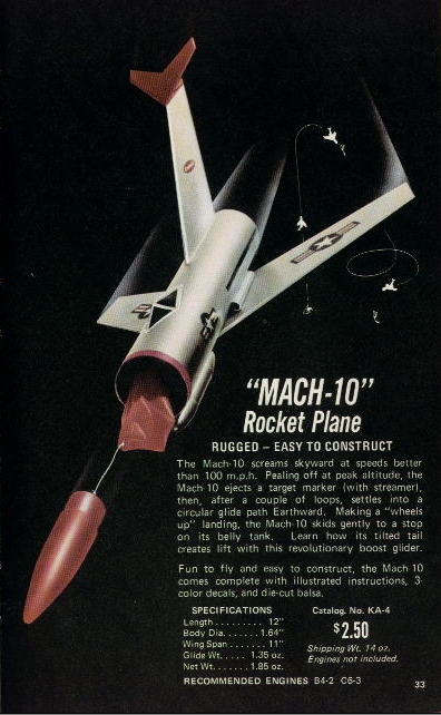
More Rockets Mach 10 Build Part 1, Parts


I had an original Centuri Mach 10 years ago. I don't remember how it flew or if I even launched it.
This is a clone kit from More Rockets to be built for a client.
Most of the parts were good quality, Some parts were questionable.
The instructions were copies of the old Centuri art. I don't know how clone vendors get away with this. Unless a Copyright has run out, these materials are still owned by Estes.

The fit of the nose cones in the bottom "tank" assembly was poor. The base of the nose cones were wider than the BT-5 diameter. I've never seen this nose cone before.

The two launch lugs were two different lengths.

The engine hook isn't spring steel. The upper bend isn't a 90 degree angle.

The engine block spacer was a split BT-20, a clever idea for an easy slide into the BT-20 central tube.


The nose cone was an original Centuri part made to fit the slightly larger ST-7 tube.
The kit includes a BT-20 central engine mount tube. The shoulder of the Centuri nose cone won't fit the supplied tube!
I'll have to substitute an Estes 20 sized plastic nose cone with the correct shoulder diameter.

The decals are printed on a white decal sheet.

I wouldn't want to use the stars and bars decal in the center. The star isn't symmetrical.


Sunday, December 18, 2016

Rocketry Show Interview with John Boren


The Rocketry Show interviews John Boren of Estes Industries.
One hour of great information on rocket design and kits!

CLICK HERE to hear the interview.

Pretty interesting to hear how some kits are designed to clear out overstocked nose cones.
No future Pro Series II models on the horizon. The newer "web only" Pro Series kits are to clear out existing parts.
Mr. Boren hints at a Sci-Fi bring back using a nose cone "You can't turn on a lathe." The model has an "Absence of color", meaning it is black.
Could it be one of these? CLICK HERE or CLICK HERE or CLICK HERE or CLICK HERE
I would doubt Estes would bring back the SR-71 Blackbird. That kit is a very difficult build.

Which Came First?


These two designs shared many of the same design elements.
Both models were short, had solar panel fins and used an existing NASA style capsule.

I always liked the Orbital Transport Laboratory designed by Ted Nomura (Shown at the upper left). It was the June 1971 winner of the Estes Design of the Month contest. The plans were printed up in the Estes Model Rocket News. The model was also seen on the cover of the 1972 Estes catalog. For the JimZ plans: CLICK HERE

On the right is the Apollo Earth Orbital Workshop designed by Ronnie Cramer. It was featured in the August 1971 issue of Model Rocketry Magazine; CLICK HERE


These two designs are enough alike that one probably inspired the other. Which came first?
Both the Estes MRN ad Model Rocket Magazines have dated covers, they didn't always arrive at your mailbox by the posted month. A June issue could arrive in mid July! These two designs were printed within two months of each other.
Magazine submissions rarely go into print the week they arrive at the publishers. Some articles will sit for months before being used.

Here's another Apollo Earth Orbital drawing from a later Ambroid glue ad.
I doubt Ronnie Cramer ever got residuals from Ambroid copying his design.


Centuri had a solar paneled kit, "Available February 1, 1972".
The Sky-Lab fins may have been spurred by these earlier designs.

Flying Engine Mount Build, Finished

I forgot the launch lug holes!
You won't need a launch lug on this one. Two holes in line through the centering rings is all it takes.

Ideally, the holes should have been punched before the rings were glued on. My rotary punch doesn't allow me to get close enough to the engine mount tube. It'll still slide on the launch rod and launch normally.


The bottom ring was punched. A launch rod was slipped through and turned against the upper ring leaving a mark for the second punch.

Here's how the launch lug fits.
This flying engine mount should be flown with A10-0t or A10-3t engines.
This is a tumble recovery rocket. Call a "Heads Up" before launch.

Saturday, December 17, 2016

Estes Long Tom, Follow-Up - Sustainer Fin Locations?

At a recent Orlando R.O.C.K. launch, Glenn S. launched his Estes Long Tom.
I looked at the fins and wondered why they were positioned up from the end of the sustainer body tube.


On the left is my finished Long Tom. On the right is Glenn's model. Notice the upper stage fin locations?
Glenn said this was his second Long Tom build. He noticed in the instructions that it showed the fins glued on up from the rear of the body tube. His second build had the raised fins.
I read and follow directions and wondered how I could have missed this.

Earlier in the instructions you are instructed to mark the fin locations with a wrap around guide.
No mention is made to make a mark 1/2" or so above the low end of the tube.

The fin gluing illustration in the middle of page 4 shows the two fins marked "J" above the tube. Look at the straight on view of the middle fin. It looks to be even with the end of the body tube.

The inset picture is from a later step in the instructions. The trailing edge is even with the end of the tube. Most all other drawings show the same fin position.

Here's the face card illustration.
The back end of the second stage is black but you can make out the fins are glued on up the body tube.

The Estes instructions are inconsistent. Is it a big deal, does it effect the flight? Probably not.
If you wanted to build it closer to the old Centuri version it's a little maddening.
I went to double check the instructions on the JimZ site but many of the Centuri plans don't come up.