Showing posts with label Engine Hooks. Show all posts

Friday, October 31, 2025

I Wish Manufacturers Wouldn't Do This, Part 6 . . .


Some kits include an engine hook that gets get bent out of shape after the first flight!  
Use SPRING STEEL, not pot metal. 
You can get spring steel engine hooks from BMS. (Balsa Machining Service)

Monday, June 16, 2025

Estes AMRAAM AIM-120 Downscale, Build, Part 6, Engine Mount Assembly & TIPS


Many kits have you glue 20/50 centering rings at 1/2" from each end of the engine mount tube. That doesn't really give enough flex for a spring steel engine hook.

The mount shown here is flipped over with the hook pointing up.

TIP: I've found the best position for the low, bottom ring to be 7/8" from the bottom of the engine tube. This allows enough flex to slide in a motor.


TIP: This is a brilliant way to lock in the Kevlar line comes from the older Semroc kits.

The Kevlar line gets a small overhand knot.
This is slipped under the upper bend of the engine hook.

In the picture, the upper centering ring has not been glued in place yet.


The upper centering ring is slid up and glued on slightly over the Kevlar loop.
The centering ring also locks the upper bend of the engine hook in place.

TIPIn all my new builds, I am incorporating heat shrink tubing over the Kevlar line for extra protection. The heat shrink tubing idea comes from Rick Randoll of New Way Rockets.

Tuesday, December 24, 2024

Estes Constellation Build Part 18, White Trim on the "1" Decal TIP

Before soaking the trimmed red decal -
Have a sheet of decal paper sprayed with gloss white paint. This will be used for the white edge. Spray a clear sheet with white getting full coverage. Let dry thoroughly. No clear coat is needed on the white sheet, the white paint seals the surface. You'll be making a composite decal, the red "1" set on the white border base.


On the left is the two trimmed red "1"s.

You'll need tweezers to hold onto the decal when soaking.

Dip the decal for 15 seconds and remove from the water.
Change the position of the holding tweezers so the entire decal is soaked.

Set the decal on the sprayed white decal sheet.
Use you rotary punch to get the upper left round edge cut.
This punch sets the thickness of the white border.

On the left is the trimmed decal with the new white border.
On the right is the second decal being trimmed.
Be sure your straightedge is perfectly positioned before cutting the white border.
You get one chance to get it right. Use a new blade.


I was surprised how well the red stayed on the white backing during the re-soaking. It didn't shift when sliding off the backing paper.


The "2" and "3" decals are wider than the "1".
It was set between the pencil lines.


And finally, the engine hook was scraped clean of paint and polished with some 400 grit
.

Tuesday, April 9, 2024

Estes Mini Bertha Clone, #TK-3, Part 4, Slightly Longer Engine Mount?


An engine block wasn't included in the original kit.
I added one, glued in so it's flush with the upper centering ring and body tube edge.
Here's why that engine hook was designed to hang 1/2" beyond the bottom of the mount!
There isn't much clearance and flex between the BT-5 and BT-20 tubes. The low bend of the engine hook scrapes along the outside of of an engine casing when slid into the mount.

It's not impossible to get the engine in the mount, you'll just have some friction when being slid into place.

I pressed the mount into place with the flat face of my sanding block. The Kevlar was fed out the back and layed to the side while pressing the mount into the tube.

The mount is certainly useable with the shorter overhang hook. 
TIP: This is a BMS 1 3/4" engine hook. The cut off ends were a little rough. I smoothed out the edges with a few passes of a small, flat diamond file. The engine slides in easier now.

With the Bertha's fin trailing edges in the way it takes a moment to work an mini engine into the mount.
I'm sticking with the modification I made.

Monday, October 31, 2022

Estes Odyssey #7235 Build, Part 9, Engine Mount


One of the 50/55 centering rings will need to be notched to allow engine hook flex.

I usually cut the notch with a single edge razor blade. You can simply press down on the blade and get a clean cut.
Notice the angle of the set blade. When cutting at this angle you can end up with sides that match the movement travel of the engine hook. 


Set the glued notched ring into the BT-55 body to hold the ends down as the glue dries.

I did cut off the finger tab . . . because I'm a big boy.


A sparse line of glue is rolled around the tube and the black retainer ring is slid into and over the glue until it rests against the top of the lower centering ring.
Fillets are then added.

The engine block ends up recessed inside the top of the mount when slid in against the top bend of the engine hook.

Sunday, October 30, 2022

Estes Odyssey #7235 Build, Part 7, Tail Cone Hook Relief

Take this step slow!
A notch has to be cut into the tail cone to allow movement of the engine hook.
Mark with a sharp pencil, 1/8" wide by 1/2" long.
Those half round vertical ribs are wider at the bottom. Keep that in mind when cutting out the notch.

Score the pencil line with a sharp knife.
I carved the notch out making small chip cuts from side to side. 
The top of the notch was squared up using a diamond file.

The sides were widened with the flat file so the 1/8" width would be consistent from top to bottom.
Check the width by sliding the engine hook in making sure it doesn't bind against the sides of the notch.

Thursday, September 15, 2022

Estes Space Shuttle Columbia Build #1385, Part 4, Engine Mount & Clay Weight


The engine hook gets a soft bend to keep the ends over the top and bottom of the engine.

Don't just bend it from the middle - 
Try soft bending it from one end to the other.


The instructions say to cut a engine hook movement notch using a knife. 

I used a rotary punch for a cleaner cut.


The instructions suggest the upper ring is glued even with the upper bend of the engine hook.

I like to overlap the upper bend of the hook. It makes a stronger mount. The upper ring did get a shallow crescent punch to fit over the engine hook.


The clay weight weighs .41 oz.
ALL the weight is used, pressed into the inside tip of the nose cone.

Friday, June 17, 2022

Odd'l Rockets F-18 Hornet Development & Build, Part 3, Wings & Stabilizers

The wings, stabilizers and rudders stayed pretty much the same from the "naked" test models through the bagged kits.
The wings are two piece.
Both the wings and forward fairings are glued together. It helps to set them against a straightedge while the glue dries. 
You can also set a medium weight (like a small paint bottle) over the joint to even things up.


Here's how the wings and stabilizers set on the body tube, directly opposite each other.

For a stable model, the wings are moved back - no space between the front tip of the stabilizer and the rear edge of the wing.


The root edges of the two rudders are sanded at an angle for a better glued fit on the tops of the stabilizers.
The two rudder root edges should "mirror" each other.
Here's how they glue onto the model. The root edge of the rudders are against the root edge of the stabilizers and touch the body tube.

This picture shows the engine mount from the later "show" model build. The test models had the engine mount with the engine hook at the bottom. This was changed to the top when I found it a bit difficult to remove the engine with the two jet engines glued onto the bottom.

Friday, May 20, 2022

Quest Falcon #Q1009 Build, Part 3, 24mm Engine Mount


I like to square up the centering rings. When they are cut at the factory the blade makes a wedge cut.

It's not necessary to do this - I sand the ends flat for a cleaner build. I always flatten the bottom ring face if the ring is even with (and visible) at the base of the main airframe tube.


I also check the tube ends.
On 3" and 4" tubes, there's a bigger chance the tube might have a rough cut.


The engine hooks need a slight curve bend.
Make the curve smooth.


The 24mm tube is white. 
The 18mm motor mount tube is yellow.

Here's the instruction drawings for the 24mm mount. You are told to repeat the same assembly for the 18mm mount.


The thick orange rings were notched for the engine hook relief and the upper ring for the Kevlar line tie.

This is not mentioned in the instructions.

Tuesday, June 15, 2021

Estes Indicator #7244 Build, Part 2, Some Parts Prepping


The fins show clean laser cutting but some of the line segments didn't match up.
These should be squared up with a block or you won't have a good root edge bond. 


Here's what I mean - 

This shows the edge sanding about halfway through the sanding. Keep sanding until the burnt edge is nearly gone.


I also like to square up and flatten the engine block and those thick 20/50 centering rings.

A squared up engine block can fit better against the upper bend of an engine hook. 
Sometimes a low engine mount centering ring is set flush with the end of the main airframe tube. Square it up and the joint will be less noticeable on the finished model. 

The finger tab was cut off because I'm a big boy.

Flip over the hook and put the cut end at the top of the mount.

The inset picture shows the bent end of the mount after hitting it with a metal file to roll off the sharp corners. This makes engine insertion easier.

Saturday, April 10, 2021

A 24mm Engine Mount from an 18mm Mount

One of my builds required changing a 18mm mount to a 24mm engine. 
Trace around the 24mm engine tube with a sharpened pencil, centered on the ring.
Cut out the inside ring with a sharp knife, just inside the pencil line.

On the right is the cut out center above the new 24mm centering ring.


Clean up the inside of the ring with some 400 grit sandpaper wrapped around the smaller 18mm engine.

Check the fit on the 24mm engine mount tube as you go - you'll want a sliding but fairly tight fit.
I like to punch some relief areas for the engine hook and Kevlar line. If there is no allowance for the hook and Kevlar, the round shape of the motor mount tube can distort.
To be sure they are centered and on opposite sides, I draw an cross on some card stock and mark the twelve and six o'clock positions.

Using a rotary punch, some crescent holes were made. Punch out just enough for the hook and Kevlar.

On the right side picture, the upper ring has an engine hook notch (top) and a Kevlar punch (bottom). The lower ring has a crescent notch for the engine hook.

Friday, April 9, 2021

Engine Hook Tape Retention

Before gluing on the centering rings,
TIP: 1 1/2 wraps of electrical tape is applied to retain the engine hook.

Start the tape wrap 1/4 turn below the engine hook. 
The tape goes over the hook and completely around the tube. 
Go over the hook again and finish the wrap 1/4 the way around, directly opposite the starting point.
This way you have a double wrap of tape over the hook.

Note the mount is flipped over in the second picture to show the other side.

I've mentioned this before - Why use electrical tape? It retains it's flexibility. and will last a lot longer than paper masking tape.

Saturday, December 26, 2020

Estes Saturn 1B, #7251 Build, Part 28, Engine Hook Notch

A notch is needed in the low centering ring to allow engine hook movement. The notch location is set between two of the booster tubes.

Slide the engine mount in place and mark the width of the hook in pencil.
The instructions imply the notch is cut and removed. I decided to make a smooth "ramp" inside.
In the upper right picture a small slot is cut and removed from the centering ring.


The sides are cut straight down, but no cut is made at the bottom of the notch.
The notch was pressed into the ring notch cut earlier. No need to remove a segment of body tube


Some glue is rubbed over the notch.


The engine mount is glued into the central core tube. 
I used my sanding block to press the engine mount even with the bottom of the centering ring.

Build time:
Make notch and glue in engine mount: 20 minutes
Total build time so far: 21 hours, 55 minutes

Sunday, November 1, 2020

Estes Asteroid Hunter #3224, Build , Part 2, Engine Mount

I was disappointed to find out the engine hook was not made of spring steel.
I usually bend them to see if it will spring back. This one didn't and was tossed.

I will use a spring steel replacement engine hook purchased from BMS.
Why replace a engine hook that bends? 
When sliding in an engine, a pot metal engine hook can bend out - and stay bent out. The next launch it bends even more to the point where it may not retain the engine at ejection.


Engine mount construction is pretty standard. 
I wanted to use a Kevlar line in place of the tri-fold mount.

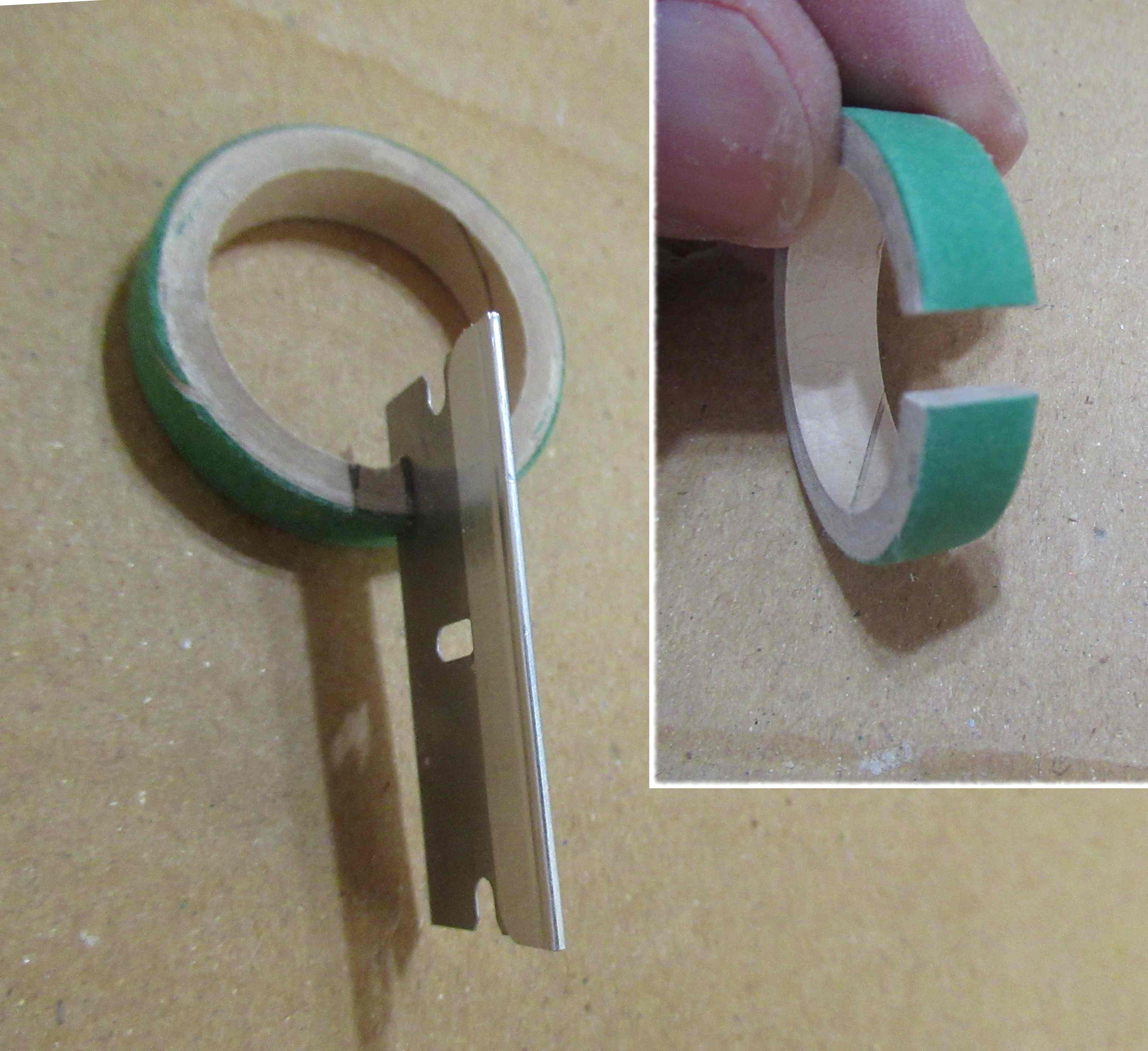
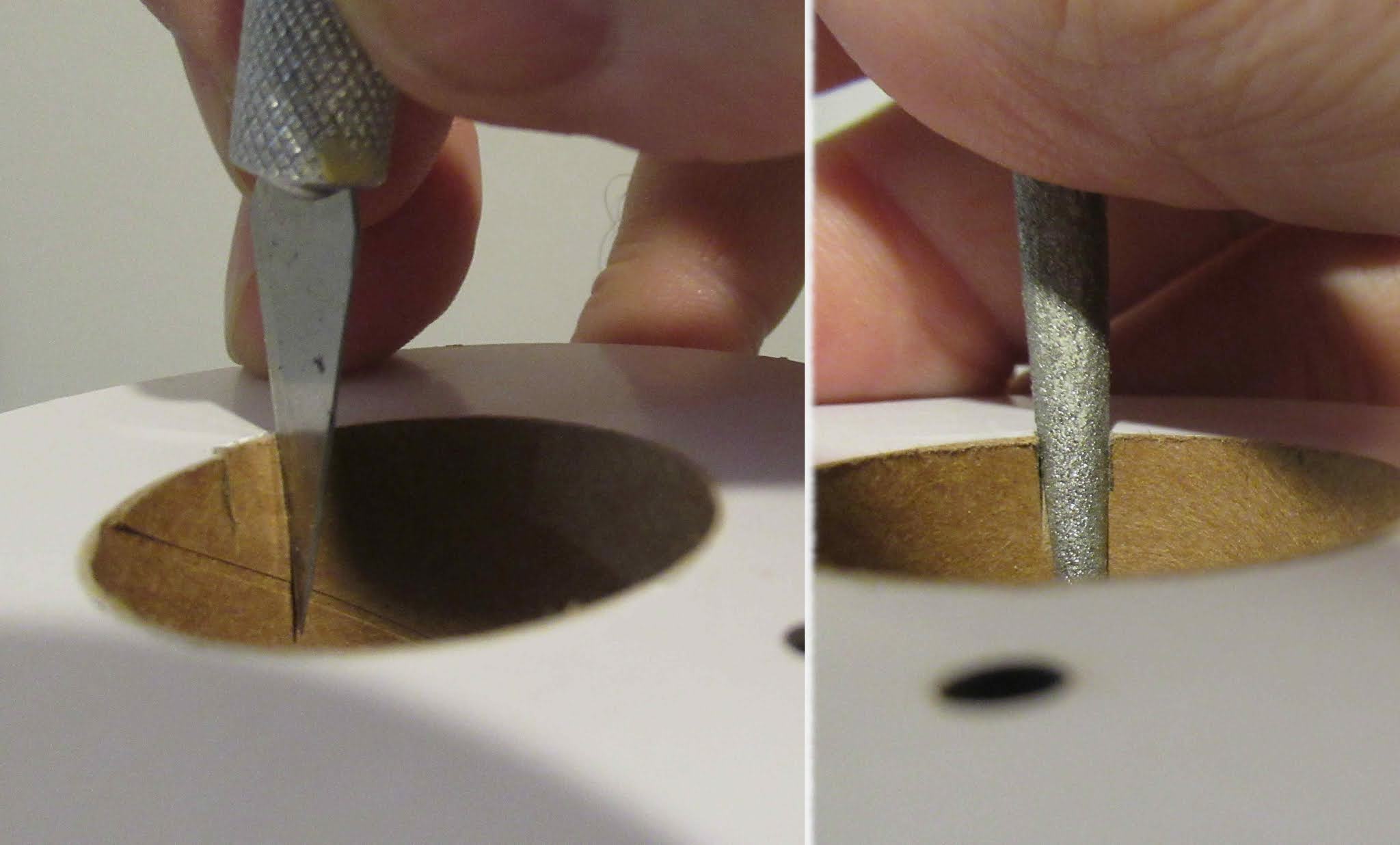
This requires a notch to be cut into the upper centering ring, shown at the right.
There isn't much space between the BT-20 engine mount tube and the inside wall of the BT-50. A doubled knot could bulge the outside tube. A bump wouldn't be seen on the outside of this design. I wanted to show another way to tie the Kevlar without that bulky knot.

The Kevlar is wound around itself three or four times and pulled tight.
The notch in the upper ring is slipped over the Kevlar line. With the Kevlar line slid below the ring, apply a glue bead fillet at the joint. 


The Kevlar end is pulled and the loop slid into the glue fillet.
The loose tail is pressed into the glue. Sometimes it's easier to use less glue to hold down the Kevlar end.

On the right you can see the twisted Kevlar wrap set into the glue. After the first line of glue has dried, another fillet is applied and the excess wiped off.

Saturday, July 4, 2020

Estes Mars Longship Build #7296, Part 5, Engine Mount


I did make a slight arc bend in the engine hook.

Over the years I've learned to mark the engine mount tube three or four times around the tube. A single line of marks can be covered up by the engine hook.
TIP: The engine block was loose in the engine tube. A dried glue bead around the outside edge increased the outside diameter.


This was a pre-production kit. The centering rings weren't notched for engine hook movement.
I used an X-Acto #11 blade to make the notch cuts.

The engine block was slid into place (without glue) until it butted up against the upper bend of the engine hook.
With the block spaced evenly from the top, a line of glue is added to the top joint.


Here's the finished engine mount with the three centering rings and black hook retainer in place.