Showing posts with label Vacu-Form. Show all posts

Monday, December 8, 2025

Estes USS Enterprise #1275, Part 29, The Tail Caps


GOTHCA!
The tail cap liners (slip-in shoulder base) won't fit into the tail caps!
The diameter of the liner is the same diameter of the tail cap. Notice the sides of the liner taper towards the right side.


The instructions say to "sand the liners until they fit 1/4" into the tail caps. I sanded using 220 grit.

The picture to the right show how much of the edge was sanded off that first shoulder.

 
After sanding, one tail cap liner slid in.

The second liner required a cut slit in the side. No amount of sanding the tapered shoulder would allow a slip fit.

Friday, November 28, 2025

Estes USS Enterprise #1275, Part 19, The Radar Dish

A hole is made in the radar dish center to fit over the sharpened dowel.

Start the hole by spinning a blade tip in the center.
Enlarge the hole using a small rat tail diamond file. By using a file to open it up, you'll end up with a rounder hole.
Careful, it's easy to make the hole too big. File a little and check the fit. 

Glue the dish using liquid plastic cement.
The "ball" at the end of the dowel tip is a drop of white glue. You might have to build up the diameter of the ball using a few applications of glue.

Thursday, November 27, 2025

Estes USS Enterprise #1275, Part 18, Fixing The Vacu Form Cracks

HAPPY THANKSGIVING!


Wood glue fillets were used to fill the joint gaps.


Here's a picture from a previous post showing the cracks that started in a thin plastic area. 

The same method is used to fill the recessed mold lines in nose cones.
Squeeze out a drop of medium super glue on scrap cardboard. Dip a toothpick in the drop and drag the tip across the crack.

It may take a few applications to build up and fill the gap.  


After it dries, sand with 400 grit.

It's better but could still show a faint separation later after paint.

Wednesday, November 26, 2025

Estes USS Enterprise #1275, Part 17, The Homing Beacon

The homing beacon is cut off the vacu-form sheet the same way the larger pieces were.
Ball point pen outline, then scoring the edge.
Break away the sides by cutting and cracking off angled wedges.

The sides are a little rough after the first cuts.

Sand the bottom flat until the edge starts to roll off.


The finished beacon wasn't perfectly round.

The instructions say to sand down the overlap seam 3/8" wide, 1/8" from the rear. The pencil marks show how wide that marking is - too long.


On the left, the overlap ridge is removed to fit the actual diameter of the beacon.

On the right, the fitted and glued on beacon.

Tuesday, November 25, 2025

Estes USS Enterprise #1275, Part 16, The Hull Pylon

The internal pylon assembly was set inside one side of the secondary hull. A pencil line was traced around the bulkhead.

Contact cement was applied on one side at the pencil bulkhead line and at the pylon doubler contact areas.
Repeat for the other side.


Before allowing the pieces to touch - carefully align. 
The pylon assembly was pressed in place.
Be sure to check that the slots line up at the back.


The secondary hull assembly.


Two small hairline cracks occurred on the forward end of the hull. The cracks formed where the plastic was the thinnest. 
I'll fix this in a later post.

Friday, November 7, 2025

Estes USS Enterprise #1275, Part 5, Cutting Out The Vacu-form Parts


I saved the large hull disks for last. 

As before, trace around the edges with a ball point pen.
Score along the pen lines.


Free up the edges for easier bending and cracking by cutting relief segment lines.


Sand the disk edges with a block.

The right side picture shows the upper and lower primary hull halves dry fitted. Note the overlap of the top half.

Thursday, November 6, 2025

Estes USS Enterprise #1275, Part 4, Cutting Out The Vacu-form Parts


Here's what I mean about the high pieces being thin at the baseline.
There was a crack in the thin area of the secondary hull.

This happened before I sanded the base edges.

A strip of the scrap plastic was cut and folded to a "V" shape.

This was glued in place over the crack using liquid cement.


Another area of concern - 
The front of the secondary hull halves were also thin.

Sand the edges on a block using 220 then 400 grit sandpaper.

Wednesday, November 5, 2025

Estes USS Enterprise #1275, Part 3, Cutting Out The Vacu-form Parts

Cutting out vacu-form parts can be a delicate operation. 
Take your time!

The oldest method is probably the best -
Draw around the bottom recess with a ball point pen. This gives you a defined line to cut on.
Score (no need to cut all the way through) along the ink line with a sharp knife.

Bend back and forth along the scored line until the flat excess cracks off.
You can break off the scrap plastic in short segments. Cut lines (like pieces of a pie) away from the scored line for easier bend and separation.


Sand the bottom edges smooth with 220 grit on a block.

You are reaching the finished edge when you notice small strings of thin plastic rolling off the bottom.


For comparison,
On the left is the dome after cutting off the sheet.

On the right, 
The dome after sanding the base. Sand off all the turned lip so the sides are flat.

Wednesday, April 5, 2023

Estes Klingon Battle Cruiser, #1274, Step 15, Warp Drives & Wings

The sides of the Warp Drive pieces don't want to stay together. When you glue down one side, the other side opens up.
Earlier posts had the interior support tubes sanded down so the edges could touch.

More liquid plastic cement with finger pressure on both sides while the glue set up.


The large wing assembly is are confusing. Darn Klingons!


Here's how they actually look. The root edges are facing each other.


The front hull piece joint needed some CWF fill, the filler/primer and sanding.

On the right the front hull piece fits well over the BT-50 main tube. Do plenty of dry fits before gluing the wing in place.

GOTCHA: Those tips above the round center area do not have to touch! If they touch you might not get the angled "down" dihedral. Most of the gap between the tips will be covered by the Access Boom Detail vacu-form piece. 
Check the decal drawings in the instructions. The outside edge of the wing should be below the centerline joint (pencil line) at the body tube. 

Tuesday, January 3, 2023

Estes Maxi-Brute Honest John (Kit #1269), Part 15, Gluing Up & Sanding The Fin Sides

Before gluing up all the fin halves - 
Wait to read Step 16. I did a fin reinforcement to stiffen the plastic fins. 
This post shows how the fin sides are joined per the instructions.

The leading edge is already glued shut and remains closed in the following steps.
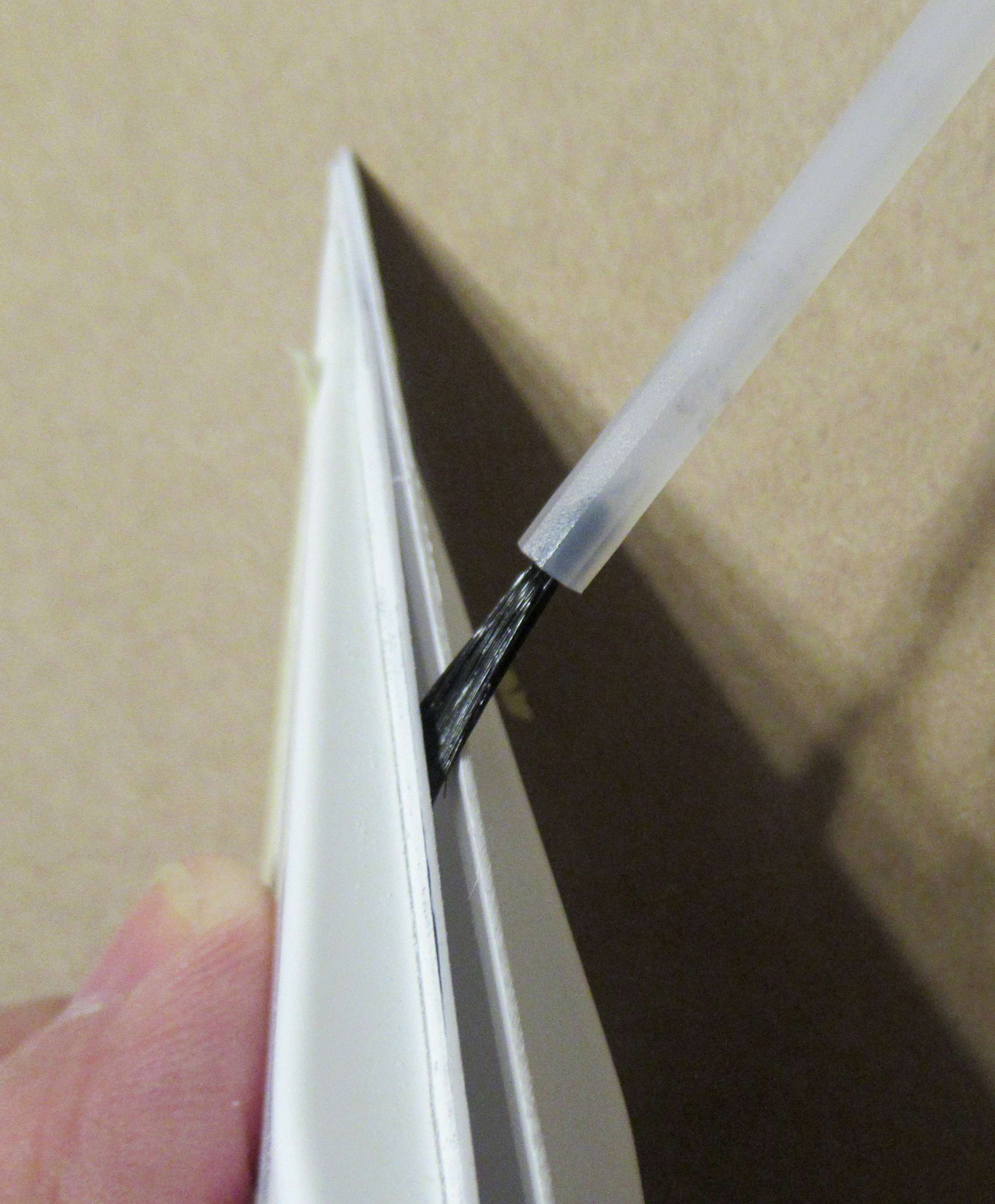
Slightly open up the gap on the root edge side a sneak in the brush to apply a wet line on both sides.
Close and hold until the glue sets up.


Where you can, open the two halves up enough to get the wet brush between the two fin halves.

Where you can't get the seam to open wide enough for the brush,
Brush on some glue over the closed edge. The glue is thin and some should seep into the joint.


After the glue dries, continue sanding using a block with 220 grit sandpaper.

Here I've started to sand down the overhang edge.
A joint has opened up - 
Brush on more glue and hold the gap closed. 

Don't sand all the way down and Don't remove every bit of the overhang lip.
Notice I traced a pencil line around the raised fin sides to better see the height of the overhang lip.

Sand very "close" the the fin side - 
Then sand and round off the remaining lip, shown on the right.

This leaves the fin a little stronger. If you were to sand to far, there is just two thin ends butted up against each other. Stopping a little early leaves a bit more contact of the plastic at the bonded sides.

Monday, January 2, 2023

Estes Maxi-Brute Honest John (Kit #1269), Part 14, Gluing Up The Fin Halves

(My camera focused on the closest edges. Look at the blurred right and left wider sides of the fins.)

On the left - 
Notice one side is higher than the other.

On the right - 
This is what you are looking for. Both sides are in line with each other. You can't count on evening up the overhang edges. Look beyond them and focus on the sides of the fins.

Alignment of the fin sides is VERY important. If one side is high, you could sand through it trying to even up both sides.


After checking the alignment on all four sides - 

Tape together the fin halves with a strip on masking tape, making a hinge. Check the alignment again before using any glue.


Open the two halves.
This allows you to apply liquid cement to the edges on the tape side.

The inset shows the Plastruct Plastic Weld glue I use.


Brush a fairly wet line down one side of the "hinge" edge. Work fast - This glue dries quickly.

Close up the fin and hold until the glue dries.
We'll glue the other three sides in the next post.

Friday, December 30, 2022

Estes Maxi-Brute Honest John (Kit #1269), Part 13, Thinning Down The Fin Sides

You are instructed to thin out the fin edge overhang to 1/2 of the original thickness. This is much like the old two-sided vacu-form fins in the older Centuri style Saturn 1B and Saturn V kits.
   

The big fin plastic halves are flexible.
Don't sand like the picture on the right - 
Sand as shown on the left, flat over two sides.
This prevents any scratching (and possible  thinning) of the inside wall.


After some scratching up the interior of the first fin half,

I taped the inside wall to protect the surface. 


Notice the forward fin half. The side edges have been thinned.

Note the inside corners are sharper, more defined than the unsanded fin in the back. 


I ran a Sharpie marker over the edges to show the thickness.

On the left is a fin half, not yet sanded and thinned out.
On the right is a sanded, thinned fin edge.

Tuesday, December 27, 2022

Estes Maxi-Brute Honest John (Kit #1269), Part 10, Spin Nozzles Units, Part 2

Mentioned in the last post - 
The curved top and bottom will be sanded through first.

On the right, the curved edges are trimmed off leaving the straight sides. 

The straight sides are trimmed off with a sharp knife and straight edge. 
Sand and clean up the straight sides with a sanding block.


Do some test fitting on the low nose cone section.

In the top picture, there is still a gap on the straight sides. This tells me I've got more sanding to do on the 220 grit wrapped around the lower nose cone piece.

Here's a better fit, all the way around the piece.


The spin nozzles will be glued on (later) with liquid cement against the molded lines around the nose cone base.

Monday, December 26, 2022

Estes Maxi-Brute Honest John (Kit #1269), Part 9, Spin Nozzles Units, Part 1


Score around the raised spin nozzles leaving about a 1/16" edge. Bend and crack off the sides.
Hang onto the larger scrap pieces. You might need them for patches on the fin edges. Anytime I've worked with vacu-form parts before, I've needed patch plastic.
Looking ahead - 
The instruction illustration shows a spin nozzles being glued in place. The drawing shows a flat edge border around all sides of the spin nozzle piece.

That's not how they end up after sanding in the bottom curve.
I taped some 220 grit sandpaper around the low nose cone piece. 
Go back and forth in a straight line (here going left to right, right to left) over the sandpaper.

The two side curves will be reduced first, the straight top and bottom edges are reached last.

Sunday, January 2, 2022

Estes Skylab #001973, Build, Part 19, Almost Ready For White Paint

And now, back to our regularly scheduled program . . . 

Here's the seam side of the low wrap before the lower launch lug was glued on.
The wrap seam fill was medium CA glue.
Squeeze a drop of CA on scrap cardboard.
Dip a toothpick in the glue and drag the drop of glue down the joint seam.
Fold a piece of 400 grit (not a sharp crease) and sand the glue in the joint.

Run a dull knife blade over the filled seam - If you can still feel a seam gap, do another fill and sand pass.


On the details wrap, you can see the joint where the corrugation space is a little wider. 

The joint seam is filled, smooth and not that noticeable.


The upper wrap joint fill.


On this build I tried to fill the joints at the tunnel ends. 

I used the toothpick/dip CA glue transfer method but I found the dried CA hard to sand. I was concerned I might sanded through the thin plastic. Dried CA is much harder than the vacu-form wrap.
I didn't sand through it. Results were just OK, I wouldn't recommend filling the tunnel joints the way I did. Some of the White/black color separations fall right on the joints anyway.