Showing posts with label E Orbital Transport Laboratory. Show all posts

Thursday, April 23, 2020

Estes MRN Orbital Transport Laboratory Build, Finished


Well, this was a fun build. I had always wanted to build one since I first saw it in the Model Rocket News. I'm happy with the finished model.

Some observations: 
The dowel attached fins are hard to line up.
There is not much room for wadding, parachute and the nose cone shoulder.
Friction fitting! (I hate friction fitted engines)

The recommended engines are the OOP A5-2, B4-2 and C6-3. Empty weight of the finished rocket is 1.60 oz. My Odd'l Pigasus (another stubby model, close to BT-60 size) weighs 2.50 oz and flys fine with B6-4 and C6-5 engines. My first launch will use a B6-4.

Wednesday, April 22, 2020

Estes MRN Orbital Transport Laboratory Build, Part 16, Nose Weight & Shock Cord


The instructions called for one NCW-1 Lead Weight! LEAD - Between the lead weights and a square of asbestos on the Centuri LIA-50 launchers CLICK HERE, how did we ever survive rocketry in the 1960s and 70s?

The lead weight weighed in at 0.12 oz.


This model is short - I'd feel better if there was a bit more weight in the nose. The nose cone was drilled out for some clay weight.
Mark the center. Start the hole with small diameter drills and work up to larger ones. Don't go too deep.
TIP: Use a wrap of masking tape around the drill bit as a depth gauge. Be careful using a wood drill, balsa chips easily.

Nearer the outside of the shoulder base is the screw eye location.


I measured out some clay to .25 oz, twice the NCW-1 lead weight. This was pressed into the drilled hole.
TIP: Notice the screw eye turned to the side so it won't contact the body tube.


The 36" long shock cord was attached to the body with a tri-fold mount.

The other end was tied to the screw eye using a Duncan Uni-Knot.
An overhand knot was tied about 1/3 the way down from the nose cone. A 12" Odd'l parachute with attached snap swivel was clipped onto an overhand knot loop.

Tuesday, April 21, 2020

Estes MRN Orbital Transport Laboratory Build, Part 15, Windows & Nose Trim


It's hard to see in the instructions picture, but the Gemini style capsule has a white circle disk on the nose and the hatch windows are white.

These would bee a tough mask. Hand painting white over black would take a few coats.


I needed something to trace around.
A 13mm "T" engine is just about the right size.

The engine casing was a close fit the to the curve of the  hatch window.
I traced around the engine casing onto the self-adhesive paper used on the previous Argus build.

The nose circle was cut inside the pencil line.
The hatch windows took a few tries - they ended up being a bit smaller than the 13mm casing.


Here's the finished capsule.
Considering the small size of the window stickers, they should stay in place.

Sunday, April 19, 2020

Estes MRN Orbital Transport Laboratory Build, Part 14, Decals, Trim & Touch-ups


Here's how the decals were set, the USA was centered between two fins on opposite sides.

The available decal sheet has black horizontal stripes. While they could work fine, I used something different.


I pulled out my sheet of Contact Paper, Blackboard Material.

Strips were cut, wrapped and trimmed on the top and bottom of the American flag decals.


A little of the body tube edge was showing up between the black nose cone and black trim strip.

On the left is the before, the right picture is after the touch-up.


Some black marker was run around the tube edge hiding the white paint line.
One of my home print decal transfers ended up spotty. You can see some white showing through on the red square.

This doesn't always work - but I did some touch-ups with a red permanent marker. I lucked out this time and didn't have to print and use up another decal sheet.

Saturday, April 18, 2020

Estes MRN Orbital Transport Laboratory Build, Part 13, Chrome Trim & Fin Gluing

The old MRN black and white picture showed the black end color  as black. The 1973 Estes catalog showed the OTL in color. I could now see it wasn't black, but reflective chrome.
Why apply the chrome wrap before gluing on the fins? It would be very difficult to apply the wrap with the fin dowels in the way.
A 1" wide piece of Monokote Chrome Trim was wrapped around the tube. A notch was cut to fit around the launch lug.

After the wrap was stuck down I pressed the chrome with a fingertip to find the punched holes. A pencil was pressed into the holes to better see the locations.

Small "X" cuts were made with the tip of an X-Acto knife. You probably couldn't punch through with a pencil tip. I didn't remove the circle, I figured the folded in corners of the chrome layer would make for a tighter fit of the dowel ends.

The fins were pressed in place with no glue.
The contact point at the bottom of the ring was marked and the paint chipped off at the glue point.

The picture on the right shows a small square of paint scored and lifted off.
A "ball" of white glue was set on the dowel end. A small amount of glue was also set on the corner of the fin to contact the rear ring.

The idea is some of the glue would be pushed out along the dowel and make a fillet bead on the outside of the body tube. There is still glue on the dowel tip going into the drilled centering ring holes. White glue is used here, it could be seen outside the finished model and will dry clear.


Here's all four fins glued in place, ready for the home printed decals.

Friday, April 17, 2020

Estes MRN Orbital Transport Laboratory Build, Part 12, Paint & Fin Fitting


After a shot of filler/primer the body was slightly sanded.
Gloss white followed.

I noticed the exposed edge of the black centering ring didn't take the paint evenly. I added glue fillet over the black and shot the white again. This time the white covered evenly.

OOPS!
Eventually - it happens to all of us. Even with adequate drying time (48 hours) I had some wrinkling of the paint to the side of the launch lug!

I let it dry for a day and sanded it smooth with 400 grit. Waited two more days after that and shot the paint again. This time it was fine.
On to the decals and trim!


The fins were also shot with gloss white. I had to punch holes in the edge of some scrap cardboard to push the dowels in. This allowed me to spray gloss white on all sides.
The end of the dowel was left clean for gluing into the interior holes.


Here's how the fins should fit with the rear contact on the exposed ring edge. In a later post I'll show how the glue points are opened up for best adhesion.


To make an easier fit in the centering ring drilled holes, the ends of the dowels were tapered.

The fins were fitted in order from the launch lug going around the tube. The marks I, II, III, IIII helped me keep track of the individual fitted fin positions.

Thursday, April 16, 2020

Estes MRN Orbital Transport Laboratory Build, Part 11, Engine Mount Gluing


The motor mount assembly is glued so the lower 20/60 ring is flush with the end of the body tube.

On the left is the rounded dowel used to apply a glue drop to the inside edge of the top centering ring/body tube joint.
The other side of the dowel has a Q-tip taped on to smooth out the glue that was set into the joint.


Here's the inside just after the glue was smoothed with the Q-tip. Perspective of the picture makes it look deeper than it really is.
With the engine mount in, the lower single ply Engine Mount Cap shroud is glued and slid in place. The black edge of the exposed black centering ring is where the lower fin tip is glued.

The double nested nozzle is glued over the exposed engine mount tube and against the lower Engine Mount Cap shroud.

TIP: Line up both of the nozzle tab seams on a fin line to visually hide them on the finished model.


Before spraying with a white undercoat, the 2 3/8" long, 1/8" diameter launch lug is glued on. Paint was scraped off for better glue adhesion.

Wednesday, April 15, 2020

Estes MRN Orbital Transport Laboratory Build, Part 10, Dowel Hole Positioning


Holes were punched and enlarged slightly for a tight fit of the dowels.

TIP: You can clean up the burr left from the punch with a sharpened dowel. Rotate the tip in the hole to dress the edges.


Here's how the fins ended up -
You can see how the "fin holder" tip overhangs the inside edge of the main tube.
The corner tips will be glued onto the lowest 20/60 engine mount centering ring.
Notice the hole drilled in the 20/50 ring for the fin dowel to be glued into. The picture on the left is the "after" shot to show what you are going for.

Lines are drawn down the motor mount tube to help line everything up when the mount is slid into the glue ring.
I used the rat tail file to line everything up then the pencil lines were drawn.


Pressing and turning the file tip made small divots (pilot holes) in the centering ring.
A 1/8" drill was spun by hand into the centering rings but not into the BT-20 motor mount tube.

Tuesday, April 14, 2020

Estes MRN Orbital Transport Laboratory Build, Part 9, Dowel Hole Positioning

The dowel hole positioning is critical. I spent some time making sure of the locations before actually punching a hole in the body tube.

Notice the dowel in line with the center line of the 20/50 centering ring.
The inside tip of the smaller triangle "fin holder" piece is glued to the bottom exposed lip of the lower 20/60 ring.
TIP: Practice punching some holes in some scrap tubing to get the correct height from the bottom of the tube edge.
An "+" was drawn on the tube with a pencil. Using a rotary punch, I lightly pressed the cutting tube on the body, just embossing a light circle on the skin of the tube. Remove the rotary punch and check the position. You can make slight adjustments before punching all the way through the tube wall.


I punched the holes a little small and opened the hole with a diamond rat tail file. I wanted a tight fit around the dowel.


The dowel was slipped in the hole, the inside corner of the small "holder" fin fit just under and against the bottom of the tube.

The picture shows two different holes, the one to the left of the fin was another practice punch.

Monday, April 13, 2020

Estes MRN Orbital Transport Laboratory Build, Part 8, Bottom Nozzle

There are two nozzles glued around the engine mount tube.
The lower, "engine nozzle" is shown in the instructions as single thickness card stock. It would be the first thing to hit the ground and get bent up. Add to that the engine is friction fitted and recessed in the nozzle. I decided to make a nested or "Super Shroud".
This is two identical shrouds, on glued inside another. After they are glued onto the model, they get a CA glue coat. The double thickness shroud ends up very strong, like plastic.

Two shrouds are formed round and the tabs glued.
Some glue stick is rubbed over the outer wall of one of the shrouds.
Press the second shroud over the glued inner shroud.
TIP: For a stronger, smoother nested shroud, rotate the outer shroud so the glue tabs are on opposite sides.

Let dry.
Cut the inside shroud overhand off the bottom with a single edge razor blade, even with the bottom of the outside shroud.

Sand the bottoms even on a block.


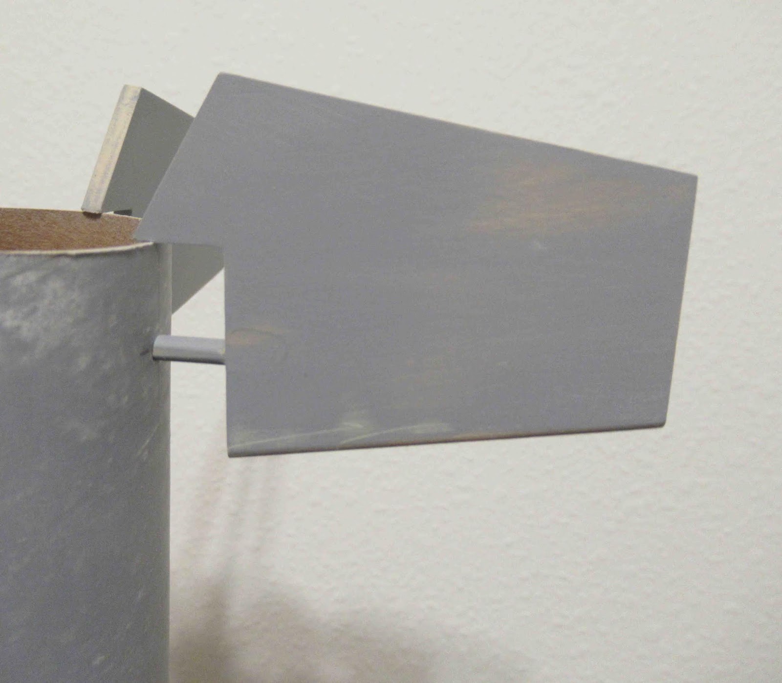
Here's how the the finished nested shroud looks. Inside you can see the top "step".
The inside step makes a double contact with the outside of the BT-20 motor mount tube.

I mentioned coating the shroud with a wipe of CA glue.
TIP: Wait until after the shroud is glued onto the model. CA glue would seal the card stock, the white or wood glue wouldn't be able to soak in.

Sunday, April 12, 2020

Estes MRN Orbital Transport Laboratory Build, Part 7, Hatch Windows

The MRN picture shows hatch windows carved into the Gemini style nose cone. I'd bet they grabbed an already finished nose cone off the catalog Gemini Titan catalog model an used it for the picture.

Here's the illustration from the Estes Gemini Titan kit showing the hatch carving measurements.


After drawing some guide lines, the 3/16" spacing from the center line seemed too wide. I drew the hatches closer together.

Those pencil circles to the right of the windows are there to remind me those areas need more CWF filler. 


The backs are cut first, straight down.


Chip cuts are made to the back cut lines.


Some 220 grit sandpaper is wrapped around a dowel to round out and smooth the bottom of the hatch cavity.


Some additional round forming to the back edge was done by pressing the smooth dowel into the cavity.

Saturday, April 11, 2020

Estes MRN Orbital Transport Laboratory Build, Part 6, Engine Mount, Nose Cone Trim

Here's the engine mount assembly drawing.
The rear of a single 20/50 centering ring is 1 7/8" from the rear of the motor mount tube.

Is that rear 20/60 ring really needed? Later another third ring is glued after the engine mount is in place.


I thought the dowel end would be glued along the top of the 20/50 ring, but the drilled hole goes through the BT-60 body tube and into the side of the ring. (To the right side of the dowel, into the center of the ring.


This is a dry fit of the end cap and nozzle over a scrap BT-20 tube.

The end cap will be a single layer of 110 lb. card stock.
The nozzle end is open and could  be easily dinged up on a hard landing. In a future post it will end up as a double layer, nested shroud.


The BT-60 body tube is short.
The shoulder base of the nose cone is pretty long! You'll want to have some room for wadding and the parachute.


The nose cone was slid in until about 3/4" was exposed. A pencil line was run around the body tube edge.
The nose cone base was cut off with a fine-tooth razor saw. The base was smoothed with a sanding block.