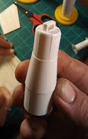
I really like the looks of the mini engine Indicator #7244 from Estes. It really calls for two stage gap staging.
There is a plastic adapter at the base of the upper fins joining the BT-50 lower tube and BT-20 upper tube.
On the NAR Facebook page, James Helman noticed the adapter: "This is the transition between the two body tubes...but as you can see the top of it has that little thing usually used to tie a shock chord onto...does enough pressure from the ejection charge go thru that little hole to deploy the chute?"
John Boren from Estes responded: "James, there is plenty of area there for the ejection gases to pass through to eject the recovery system. I've never had it not work yet."
The instructions show both tubes glued into the adapter. The small parachute is ejected at the nose cone joint: CLICK HERE
 If I were building the kit I'd cut off the flat adapter top with the shock cord tie loop. That's me - old school, concerned about enough of the ejection charge getting through the small sides of the shock cord tie loop.
 I remember this illustration from the 1971 Estes catalog.
Who knows, maybe the redirected venting might act as a baffle. Well, until the ejection heat melts through the plastic adapter top.


I'm with you on that one. My rule of thumb is to have the same amount of venting area as the diameter of the motor involved. Then there's the deterioration of the plastic, the clogging of the small hole, and the charring of the cord tied to it. Uh, maybe the latter isn't an issue here?
ReplyDelete