Tuesday, October 31, 2017

Odd'l Rockets F-104 Starfighter Build, Part 4, Intake Dressing


There will probably be a bit of the glassine layer that will flop back and forth like a hinge. It's like the thin layer left after you file your fingernails. Knock it off with some 400 grit and light sanding.
Here's the cut and contour sanded intakes.
They are both as consistent as I could make them.
Like most any other building step - Slow down, take an extra few minutes in each step. The time you take will be reflected in the finished model.


Here's the underside of the intakes.
Look at the rear left, the edges ended up wider for a smoother transition against the body tube contour.

Monday, October 30, 2017

Odd'l Rockets F-104 Starfighter Build, Part 3, Intake Cutting


Cut out the intake pattern included in the kit.
Wrap around the length of BT-20 and lightly tape in place.
Trace around the pattern with a sharp pencil.
Remove the intake template and trace a second intake (under the first) on the opposite side of the tube. Be sure it is centered under the first intake and lined up with the rear edge of the tube.

USE A NEW, SHARP KNIFE BLADE to cut out the intakes. Take your time, don't try to cut through with a single pass. Go light and try for a smooth cut line.


First, sand off any rough edges using 220 grit sandpaper on a block.


Second, wrap 220 grit around the BT-50H main tube and sand a slight curve to the edges of the intake. Go lightly back and forth in a straight line. The cleaner the intake edges, the cleaner the finished look of the model.

Sunday, October 29, 2017

Headband Light Tool TIP


I know, not much of a Halloween costume . . . yep, that's me - 

Here's a tool I hadn't used before tonight.
I bought this headband light a year ago at Home Depot. It seemed like something I'd use if the power went out in a hurricane.
I'm cutting out some custom centering rings for a future blog build. (Any guesses what model it is?)

My work area seemed a little dark so I tried the headband light.
The picture on the right shows the difference. The extra directed light really helped!

Odd'l Rockets F-104 Starfighter Build, Part 2, Engine Mount


The engine mount construction is pretty typical.

The 150 lb. Kevlar line is attached like many of the Semroc kits. The tied loop is under the upper bend of the engine hook.
The 20/50 centering rings are notched for the engine hook (see inset picture) They are slid over the hook into position and fillets are applied to either side joint.

TIP: You might find it easier to slid the rings in place (dry) and apply the glue after the rings are in place. Don't worry, they won't move during thrust.


Look to the inset picture first -
The Monokote chrome trim piece wrap is started under the engine hook. Continue the wrap around the tube lining up the edge of the wrap with the end of the tube.
Lift the engine hook and finish wrap the end under the hook.

Saturday, October 28, 2017

Odd'l Rockets F-104 Starfighter Build, Part 1, Parts

Some of the upcoming kit development has been covered already on the blog.
To catch up on some of the new parts development, CLICK HERE


Above shows all the kit parts.
Note the decals are from the German F-104, much like the Centuri version. Germany's Air Force purchased many F-104 jets.

The parts of interest:
The vacu-form canopy, the same used in the F-16 kit. Centuri used the same molded canopy in all of their Fighter Fleet kits.

The thick dowels will be carved into the wing tanks.
To the right are the split nose cones for the jet intakes. In the picture the bottoms have been contour sanded to fit the curve of the main body tube. For the kit, the nose cone will be cleanly split, the builder will sand the bottom contour. (Don't worry, it's easier than you think.)

The printed cardstock piece is the intake template. This is wrapped around a BT-20 and will cut to fit the main body tube. This intake is much like the ones on the Estes Lynx and Scorpion kits, but larger.

Friday, October 27, 2017

Centuri F-104 Starfighter and Odd'l Rockets F-104 Background and Comparisons


The Centuri F-104 Starfighter was introduced in the second 1977 catalog.
The Fighter Fleet series must have been quite successful, there were three introduced in 1975, two more designs followed. The picture above shows the last two models.

These models (and others from Centuri at the time) had wings, fins and details die cut from thick mat board stock. This heavy card stock was fairly durable and easier for younger builders to use. There was no grain to fill in thick mat board fins. Older, more experienced builders hated it.


The upper left picture shows an original Centuri F-104 build supplied by Lonnie Buchanon.
The intakes are folded from cardstock into a long rectangle shape. The intake cone is a profile triangle. Below this is the Odd'l Rockets version with the intake cut from a body tube.
On the right is the comparisons between the original Centuri kit to the left. The inset picture to the right is the new Odd'l kit. The tail section on my version is taken directly from a side profile of the real F-104 jet.


Here's the first prototype. Many small adjustments were made before the kit will be released.
The wing tanks were enlarged to the correct scale size. The tail surfaces were adjusted and the decals tweaked. 
This is one of the more complicated kits I've ever produced. I wanted it to be a tribute to the Centuri model while improving the design.

Wednesday, October 25, 2017

Estes Curvilinear #3231, Finished


I like squatty, stout rockets. This one is perfect for the schoolyard field.
I was expecting trouble with the fit of the tail ring but it slid in easily.


Here's the twins!
It also works well in the orange. The orange will probably become part of my active fleet. It could easily replace my old stretched Quest Cobalt (Orange) with Estes A8-3s and Quest A6-4 engines. The now retired Cobalt has had 16 flights since 2012.

Tuesday, October 24, 2017

Estes Curvilinear #3231, Build, Parts 12, Ring and Engine Mount Gluing

The rear ring is pretty tight, held in place by friction alone.
I did apply a drop of medium CA at the rear of each joint to lock it in place. The nose of the model was held down so the CA glue ran into the fin/ring joint.
Be sure the fins are lined up on both sides of the slot before applying glue.

Here I'm marking a glue applying dowel to place a ring of glue inside the body tube.
The rear of the engine mount tube and main air frame tube are both even when glued in place. The dowel is set beside the mount and a pencil line marked with the top of the dowel just below the upper ring.
On the right is the ring of glue around the top of the dowel.

Set the dowel in the tube up to the pencil mark. Roll the glue bead in the tube. Re-apply until you have a glue line all the way around inside the tube.

Slide the mount in place and twist until the engine hook is in line with the launch lug. Fillet the bottom ring and inside body tube joint.

Sunday, October 22, 2017

Estes Curvilinear #3231, Build, Parts 11, Kit Name Decal

If you've followed the blog, you know I don't normally include the Estes name decals. Everybody at a club launch knows who sold the kit. The only time I use a company logo is on a OOP clone model, like a Centuri kit.


Notice the difference in the width of the kit decal against the decal on the face card. The face card decal (maybe prototype build picture?) isn't as long.

When I worked at the print shop I spent a lot of time on a phototypesetting machine. I learned proper letter spacing and how to set type on a curve.  

 
On the left, look at how the C and U but up against each other. The C isn't following the curve of the set letters.
The C was cut off and placed so it better followed the flow of the line. This decal lettering probably wouldn't bother anybody else, just me!

Friday, October 20, 2017

Estes Curvilinear #3231, Build, Parts 10, Nose Cone Decals


I didn't check the clearance of the black border on the nose cone decals. After soaking the decal I could see I cut right into the top circle of the white row!

Quick fix - just cut off the top white dot.


GOTCHA - Hold any decals (that have a dashed black border) up to a bright light. It's the only way you'll see the white ink before cutting it out and soaking the decal.


TIP: If you look down the rocket body sometimes you can use the fin reflection for an alignment line.


Here's the nose cone with the chopped decal in place.
Who'll notice and who cares.

Wednesday, October 18, 2017

Estes Curvilinear #3231, Build, Parts 9, Tape Reveal and C/G


The tape was pulled and the color separation was pretty good.


The ring was slid into place. The color separation is sharp between the ring and fin slots.


Here's why the engine mounts weren't glued in earlier. I have to find the center of gravity (C/G) of the model with 13mm engine mount in place.
With the 5/60 mount slipped in with an A10-3t engine, the balance point was 3 1/2" from the rear edge of the main tube.

The 18mm engine mount was inserted with a B6-4 engine in place. I doubt I would ever use a C6 engine in this rocket. Bits of cay weight were added and stuck on the outside of the nose cone until it balanced at 3 1/2" from the rear.
The total clay weight added to compensate for the 18mm engine mount was .16 oz.

Tuesday, October 17, 2017

Paint Questions


This blog post may contain information I've posted before. But there are always new
blog readers who may not have found things from posts that go back a few years.
Please remember this is my experience, your technique and brands of paint will probably vary from mine. Jeff asked some questions in an email, here's my response:

Hi Jeff,

I do use the Rusto 2X paints - but - 
They have a chance of spraying out a rough "cottage cheese" when right off the shelf or after long periods of storage. Always spray about 10 passes on scrap cardboard to clear the pigment in the spray tube.  Be ready, the rough stuff can happen twice (start and stop, start and stop) when a can is new. This seems to happen most often with 2X Gloss White.

I don't use flat finishes at all on rockets, unless I was entering a scale competition. Flat finishes are a magnet for dirt and finger oil. I spray gloss and leave it be.
There is a picture on the cover of an older Sport Rocketry magazine where Chas. Russell is holding his scale model. He is wearing white gloves to keep the flat finish clean.

I also don't spray my models with a clear coat. In humid weather all clear coats become soft and you will leave fingerprints in the finish.
At one time I sprayed clear coats on and was initially happy with the shiny look - but one day at a hot Summer launch left fingerprints in the softened acrylic clear coat. I sometimes use some Future Floor finish (also a acrylic clear coat) on a decal, but I only roll over the decal with the Future on a Q-tip "brush".  

Regarding re-coats -
You can recoat (lay down another sprayed coat) between 5 minutes to 30 minutes after the initial spraying. If you wait longer than an hour the paint has "skinned over" but there is still some wet paint underneath that. If you spray over the not totally dried paint you'll get wrinkles. If you spray once and wait too long for a re-coat, don't spray, give it a few days to dry.

Chris Michielssen
www.oddlrockets.blogspot.com www.modelrocketbuilding.blogspot.com

Monday, October 16, 2017

Estes Curvilinear #3231, Build, Parts 8, Paint and Masking

White undercoats were sprayed.
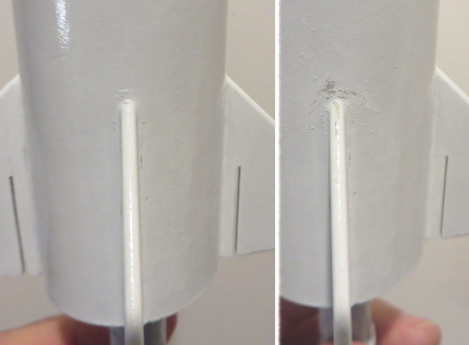
On the right shows the fillet blobs after they are sanded. You don't have to take this sanding down to the surface, just knock down a little more than half.

I wanted to use the Rusto Metallic Silver on the body tube. Normally you would paint the body, mask to expose the fins and shoot the second color on the fins.
The Rusto Metallic colors can lift when the tape masks are pulled up. For that reason (and past bad experiences) you don't want to apply masking tape over the Metallic paint. I'll do this paint mask in reverse by painting for the fins first, then masking them off and spraying the body tube metallic silver.

I'm building two models in two different fin and nose cone colors. One will be in orange, silver and black, the other in purple, silver and black. The face card show the model with purple fins and nose cone.

The lower end of the model was sprayed with orange on one and purple on the other. Concentrate on getting a good coverage of the fins. The nose cone was sprayed off the model.

Thin strips of clear Scotch tape were set down the root edges of the fins.
TIP: To mask around the rounded leading edge, sett one side down first then roll the tape around the rounded leading edge. Lightly apply pressure on the tape edge with your thumb trying to get the best half circle you can.
Continue the tape line down the other side of the root edge.
This type of turn masking takes practice, you might have to lay down the tape a few times to get a smooth rounded seal around the leading edge turn.


Here's the other build, painted in purple. The camera tends to photograph purple as a dark blue.

Masking tape was set over the remainder of the fin.


Whatever orange or purple was over sprayed was hit with another white coat. The first coat of orange and purple didn't quite cover the color underneath. This white coat was lightly sanded after it dried.


The metallic silver was then shot.

Sunday, October 15, 2017

Estes Curvilinear #3231, Build, Parts 7, White undercoat and Tail Ring Paint


The engine mount was slipped in with a painting wand in place.
A paper towel was rolled and stuffed into the back end to keep any paint out.
White undercoats followed.


The black Rusto Metallic paint is perfect for the tail ring.
After the rings got primer/filler and sanding a white undercoat was applied, then some light sanding with 400 grit.

Masking tape was wrapped sticky side out on the engine casing atop a painting wand. The rings were stuck on the tape and spray painted.


The interior edge of the rings were swiped with a permanent marker. About 3/16" of the inside edge got the ink.

Saturday, October 14, 2017

Estes Curvilinear #3231, Build, Parts 6, Fin Gluing and Ring Fit


The CWF on the fins was sanded with 220 then 400 grit.

The root edges were sanded so any primer was removed. The area around the root edge were sanded a bit more than the fin faces for a good fillet bond.


The filler primer was scraped off and the fin lines re-drawn.

The trailing edges of the fins are even with the end of the tube.


After all four fins were glued on, the tail ring was test fitted. Don't glue on until after painting the ring.
I did have to use a folded over piece of 400 grit to clear the slots on two of the fins. Don't sand too much out of the slots, you want the balsa to fit close on the ring.


Friday, October 13, 2017

Estes Curvilinear #3231, Build, Parts 5, Tube Marking and Ring Fill


Finally, a kit tube marking guide that matched up when rolled around the tube!

This is the back end with the crimp. It'll never be seen under the tail ring. The back end of the inside got a wipe of medium CA.
The launch lug is glued in place directly in line with the engine hook.


Filling the tail ring inside seam? I did because I didn't know how much would be visible when it is glued in place.
(So you know, you really couldn't see the inside seam on the finished model.)


The engine mount was slipped on a finishing dowel wand for a coat of primer/filler.
Don't glue the engine mount in so you can compare engine mounts and the different C/G later on.

Thursday, October 12, 2017

Estes Curvilinear #3231, Build, Parts 4, Fin Prep

Sorry about the lack of daily posts -
I'm visiting my Mom in California and have to do my Internet at the local McDonald's!
Mom doesn't have WiFi (and at 88 years old she doesn't want it either!)


The laser cutting was so clean, the thin tail ring slot was left on the sheet when the fin was removed.


The slot fit is very good on the tail ring, almost too good!
With the ring painted black off the model, the close fit slot will make a close, straight color separation.


The fin grain was filled off the model with one coat of CWF.
I folded up a strip of copy paper and slid it into the slot to keep the filler out when it was brushed on.
Before the CWF sets up, wiggle the paper so it doesn't get glued in place.


It had to happen . . .
There's not much holding the center strip on. Glue it on and sand some more. Luckily this break only happened on one fin.