Showing posts with label Test Fitting. Show all posts

Wednesday, May 6, 2026

Micro-Maxx Estes Fat Boy, Part 6, Fin Grain & Body Tube Seam Fill


Before printing the decal (and wasting a decal paper sheet)
A test sheet was printed on 20 lb. copy paper to check the fin decal sizes.

These are a tight fit with an even border around the custom drawn letters.
The fit seemed good and the water slide decals were printed.


Here's the fins after a CWF fill and sand with 400 grit.

Filler/primer spray follows then more sanding to surface with 400 grit.


The fin gluing line had the filler/primer scraped off.
Filler/primer seals the surface. Wood glues won't stick as well on a sealed surface.

After scraping, redraw the root edge pencil lines.

Thursday, November 21, 2024

Enerjet by Aerotech Strong Arm Build, Part 17, Adapting A Painting Wand


I use painting wands to hold my rockets horizontally when spray painting.
The wand is a 1/2" dowel shoved into a used 18mm engine casing. 

This is too small a diameter to fit this larger rocket engine mount.
I wrapped some corrugated cardboard around the casing and closed it up with tape. To fit the 29mm diameter mount, the cardboard is just over a full wrap around the casing. This wider diameter gives a good friction fit. 

With the dowel wand slid into the mount,
Some masking tape is placed sticky side out inside the main body tube.

A rolled up paper towel is press into the area around the mount and up against the inside wall of the main tube.


Any open areas are covered with additional pieces of masking tape.

Now the rocket can be spray painted without getting any paint inside the low end.

Enerjet by Aerotech Strong Arm Build, Part 16, Setting The Lowest Centering Ring

I'm back from vacation, hoping to paint the lower body assemblies - but, it's been raining! So, onto other steps.
 

Check both sides of the centering ring, pick the smoothest side to be exposed out the bottom.

On one side, there was a chip. I marked this side with "X's". This side will be facing up, not seen. 

The low edge of the body tube is slightly "squared", out of a perfect round. The four fins are locked into the rings and pull in the body tube. 

It would be very difficult to "slide" the ring in with the tube slightly out of round. 

On the left, I sanded an angle into the edge to make the insertion easier.


Notice the laser charred edge has been sanded.

The center of the ring also got a taper to slide over the engine mount tube.


The ring is slid in and rests against the root edge tabs of the fins.

Here I've applied a wood glue fillet around the ring/tube joint.

Tuesday, June 11, 2024

Semroc Wac Corporal Build, Part 9, Fitting The Tail Cone


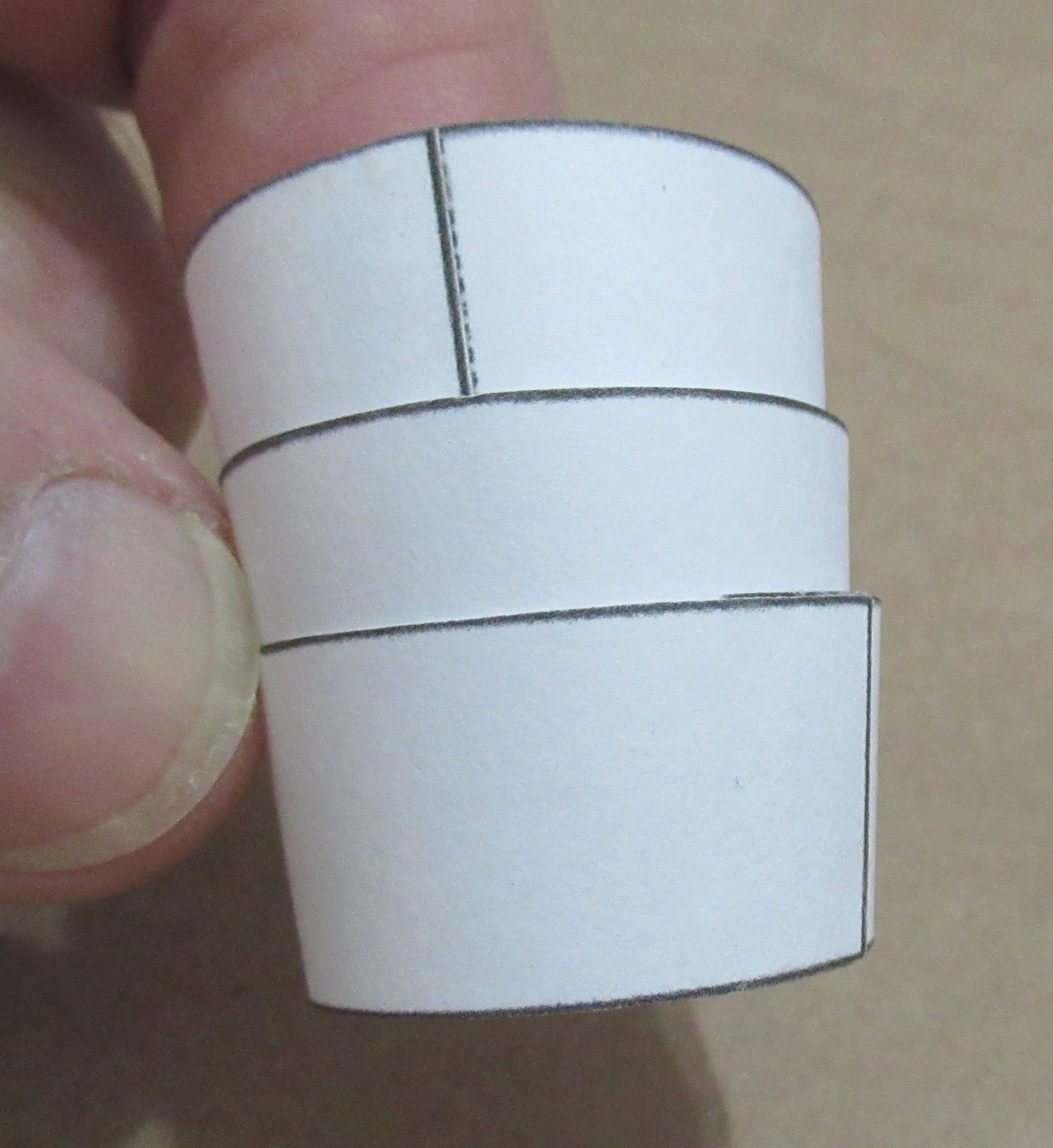
The kit supplies one tail cone shroud printed on cardstock. I rarely get a good fit onto both tube diameters with one shroud.
I scan and copy at least three of them onto 110 lb. cardstock. Assemble all three - one of them should have the best fit.

Do plenty of dry test fittings for a smoother final look.
One shroud on the left is a poor dry fit, both ends are a bit wide.

On the right, one of the other shrouds and a better fit. Both the middle centering rings have been dry pressed into the wide end. The second ring is outside the shroud top and gives you an open edge for gluing and a slip fit of the ST-11 main tube. 


The lower ring is glued in place, even with the end of the motor mount tube.

I use the flat face of my sanding block to press the ring even.
TIP: There was still a very slight gap in the small end of the shroud. I wanted to increase the outside diameter of the low ring.

I applied a thin line of wood glue. Smooth and even it out using a fingertip on both sides of the glue ring.

After it dries, run a finger around the ring and you'll feel high and low areas. Some 400 grit will take down the high spots.

Monday, January 16, 2023

Estes BOSS Kit #7316, Build, Part 9, Lower Fin Gluing

The low end fins are glued on, the motor pods haven't been glued on yet.

Note the tall fin is set 1/4" up from the end of the tube.
The tabbed fin (notched for the large disk) is even with the tube end.


I did a test fit of the disk. 
It wasn't as tight as I would like.


Look at the round index stock (overlay) and how it ended up when glued over the balsa notches - 
It wasn't a perfect fit.

A little bit of the disk and notch were trimmed until the fit was closer.


The fit is much better now.
I wanted a tight joint for an easier fillet later on.

Wednesday, November 9, 2022

Estes Odyssey #7235 Build, Part 16, Inside Rear Engine Fit?


The trimmed "L" tube is glued onto one of the lines on the BT-55 body tube, 1/2" from the rear. 

After the glue dried, I sprayed some gloss white into the tube ends. The inside surfaces were sanded with 400 grit around an engine casing to smooth the wall.
Another white spray followed to seal the visible rough surface. A little more sanding followed.

I did a dry test fit of the inside engine assembly.

All the launch lugs should end up even with the rear of the BT-55 main tube. 

With the lugs ends even, notice the forward points of the vanes extend beyond the angle cut at the tube front.

Looking at the face card picture - 
The vane tips are inside the edge of the cut tube.

Visually, I think the vane tips should be inside the angled tube edge. 
I'll have to shorten the assembly to bring the vane tips just inside the outer tube edge.

Wednesday, March 23, 2022

Estes Space Ship One, Kit # 2191, Build Part 3, Engine Mount Fitting

GOTCHA: Notice the engine mount tube was white and in this post is now brown. I ruined the kit supplied brown tube after gluing the centering rings in the "compromised" position before rounding out the tail cone hole so the ends could be even.
The rings were removed from the white tube. A new brown BT-20 tube was cut.
   
I had to round out the oblong hole using a half round diamond file.
When the hole was wide enough, some 220 grit sandpaper was wrapped around a used engine casing until a scrap BT-20 finally fit.

This took too much time to fix. I wonder how many of these kits were tossed in frustration or incorrectly assembled with the engine mount in the wrong position. 
This might be why so many were unstable before the extra 1/2 oz. of clay weight was added? (Remember, four pats of clay nose weight were included in the revised kits.)

For a better fit of the rings in the sloped tail cone, the edges were slightly angled using a sanding block. Notice I'm sanding both rings at the same time for consistent angles.

TIP: On the right - don't remove the turned over outside edges. This will leave you with a wider gluing edge.


TIP: When gluing in an engine mount you can slide in an expended engine for more support in the thin wall BT-20 tube.

Here's a correct fit of the engine mount, all the way through with the BT-20 engine tube and tail cone ends even. Whew!

Tuesday, December 21, 2021

Estes Skylab #001973, Build, Part 9, Adapter & Third Stage Wrap


Double check the Third Stage Wrap to be sure you know the top and bottom. I marked mine TOP on the inside wall in pencil.


Tape the wraps down before spraying and adhesive on the back.
Notice the wrap is a little taller than the top of the body tube.

The instructions show the Third Stage Wrap being glued  down before the Body Wrap (adapter) Reduction.
GOTCHA: I'd recommend sticking down the Reduction (adapter) wrap first, then apply the Third Stage Wrap.
I had what I thought was a near perfect fit of the Reduction (adapter) wrap by itself before the Third Stage Wrap was in place. 
I followed the instructions placing the Third Stage Wrap first. That spaced out the fit of the Reduction adapter fit making a gap at the butt joint.


I had to cut a small slice around the low end of the Third Stage Wrap as it was laying over the top edge of the cardstock shroud. This should allow the vacu-form reduction gap to close up a bit. 


This picture shows a dry fit. The gap is shown  before the thin slice was cut from the bottom of the third stage wrap. 
After removing a bit off the Third Stage Wrap, the gap is still there, but no where near as wide.

Tuesday, December 14, 2021

Estes Skylab #001973, Build, Part 2, That Darn Reinforcement Ring!

GOTCHA: It seems like the internal reinforcement ring has always been a problem.

Too many first timers (I was a once first timer) assume that it will just slide in after glue is applied.
You will have to cut out a small segment to get a slip fit.

Be sure you have the correct reinforcing ring, it is the 1" length of tube.

Try a dry fit or the ring - it won't easily slide in.
Don't try to force it!

The picture on the right shows the rough edge of the body tube. The larger the body tube, the harder they are to cut clean. Square up the tube edges with sandpaper on a block. 

Cut one straight line through the ring using scissors.

Set the ring in the tube and check the overlap. This is how much will need to be removed for a good fit.

It's best to cut the segment a bit short and sand to fit.


Sand and square up the ends. Check the fit.
Repeat - 
Repeat - 
Repeat - 
Until you get a good fit.

Tuesday, September 21, 2021

Estes Super Mars Snooper #7309, Build Part 10, More Shroud Fitting


Here's the first dry fit of the shrouds.

Notice the joint between the two shrouds is a little off. 


You can reduce the high spots with a little sanding on a block.


This is what I was shooting for - a cleaner, tighter joint.


And check the launch lug slide and alignment before gluing up the shrouds.


This shows a little more glue than what was needed.

When the shrouds were slid together, I had to quickly remove the excess with a Q-tip.

Monday, September 20, 2021

Estes Super Mars Snooper #7309, Build Part 9, Shroud Forming


The Mars Snooper kit was always a challenge with three shrouds that required a good fit and had to line up for the long launch lug to slide through. This assembly will take a few daily posts.

I did my regular shroud forming in the heel of my hand by pressing a clean dowel over the shroud.

Think of the dowel as a hand on a clock. The dowel is rotated in an arc counter-clockwise while pressing into the shroud. 
I also use the dowel when gluing on the tab, it gives me something to press against. Pressing the burnisher against the dowel also rounds over the glue tab and shroud edge.

TIP: Try using less glue when gluing together cardstock shrouds. It will dry faster using less. Just be sure you have a uniform film of glue that covers the entire contact area.


Again using the dowel inside the shroud for burnishing the glue joint.
Dry fit all the centering rings before applying any glue!

TIP: You'll get a better fit by sanding an angle onto the edge of the rings. Sand the same angle as the sides of the shroud it will fit into.
The slight edge slant can prevent distortion of the cardstock shroud. Sometimes you can see a ring impression if too much placement pressure or glue is used.

Wednesday, August 4, 2021

Estes DARC-1, #7307 Build Part 13, Motor Mount Fins & Interior Assembly


The smaller central fin is glued 5/8" forward from the rear of the tube.

The root edge was set down on the tube to mark the glue area for light scraping. The scraping exposes the bare tube for better adhesion.

Note: The fin is flipped here - see the correct position in the next picture. The fin is swept forward.


The fin is glued on the tube.
Directly in front is the shock cord retainer ring.

The inset picture shows the knot around the ring. Tie on the shock cord, then slide the ring down from the front into a glue ring. 


This is the finished central core tube assembly. 

The second shock cord is slid into the pre-cut slot in the ring. Tie a double knot. 
This is a dry fit of the central core, recovery compartment and engine mount tube.

Notice the upper fin slides into the raised nub at the top of the shroud body. The low front of the fin slides into the slot in the recovery compartment. 
That fin holds the parachute in the recovery compartment during boost and coast phases.

If the fit of the upper fin is too tight, carefully sand down a little from the top of the fin. Everything should easily slide together.

Tuesday, August 3, 2021

Estes DARC-1, #7307 Build Part 12, Wing Skids

The wing skids (laminated C parts) are glued on the underside of the wing fins into the square area on the outside edge.

In my build, the four piece laminated width was a little wider than the glue area. The right side picture shows the overhang. 

On a dry fit (no glue) I traced a pencil line around the C piece unit.

The penciled area was sanded to remove some gray filler/primer for a good glue bond.
The C block piece will still overhang the edge and be sanded smooth after the glue dries.

The overhang was sanded even with the outside edge of the wing with a sanding block.

This exposed raw balsa grain which required some filling with CWF and another shot of filler/primer.

Tuesday, March 9, 2021

Estes Hex-3, #7263, Build, Part 5, Fitting The Base, Gluing The Engine Mount

The instructions imply that the base plate is glued onto the rear edges of the main body shroud. I prefer to glue the plate just inside the edges. Don't glue the base plate on yet.

GOTCHA: The instructions say to glue on the base, then slide the engine mount in from the top. In a dry fit, I couldn't get the upper engine mount centering ring through the top hole of the shroud. I decided to glue the engine mount (a friction fit) in from the wide shroud bottom  - then glue on the base plate. 
All this is shown three pictures below:


Using no glue - test fit the base plate in the shroud.
The instructions don't mention, 
Sand an angle on the edges of the base plate. Make the angle is about the same as the sides of the main body shroud.


A test fit showed the corners needed a little more angled sanding to allow an easy fit just inside the body skin edge.


A line of glue was set around the upper ring of the engine mount.

The mount ring was pressed into the top end of the shroud. Center the engine mount.
Now, while the glue is still wet . . .


You can mold the bends to a rounder shape around the top of the centering ring.

Burnish them into more of a rounded shape around the engine mount tube. You only have to round off the top upper edge at the fold creases.