Showing posts with label Fin Can. Show all posts

Wednesday, April 24, 2024

Old Estes Parts, Part 2

Here's that same BT-30 (from a post a few day's back) with a nose cone a fin unit.


The plastic fin unit was re-purposed from those used in fireworks. 
The fit over the end of the BT-30 tube is very good.
The fin unit and nose cone are listed in the 1960 Estes catalog. The fins used in the Sky Bird and Dirty Bird designs.
An illustration for both parts is in the second 1961 catalog: CLICK HERE


The nose cone shoulder slips over the body tube edge. This is another fireworks piece.
These plastic parts were phased out as balsa equivalents replaced them. The manufacturer's probably didn't want to associate with any ties to fireworks.
Thanks again to Lonnie Buchanon for lending me these parts.

Thursday, October 5, 2023

Estes Black Brant XII, Kit # 9723 Build, Part 21, Attaching First Stage Fins

This illustration (second stage) implies that both parts of the epoxy mixture are squeezed our of the tubes onto the fin tabs. MIX the two part Epoxy before applying to the model. Wear gloves! You might have an Epoxy allergy or could develop one from exposure over time.

TIP: I didn't apply epoxy to the fin tab, then slide in the fin. That would squeeze out epoxy onto the outside surface of the model. You might end up with a strong fillet, but it would be a mess to clean up. 
I neatly applied epoxy into the slot, then slid in the fin tab. 


I had to sand a little bit on the TTW tabs for a easier fit.


Yellow glue was used for fillets where there was a wood to Kraft tube joint. The glue was applied using a Q-tip. 

Epoxy was used inside where the fin tab contacted the plastic outer fin can tube.


Here's the finished lowest fin can. Notice the gap between the upper end of the root edge.

Wednesday, May 25, 2022

Quest Falcon #Q1009 Build, Part 7, Removing The Bumps


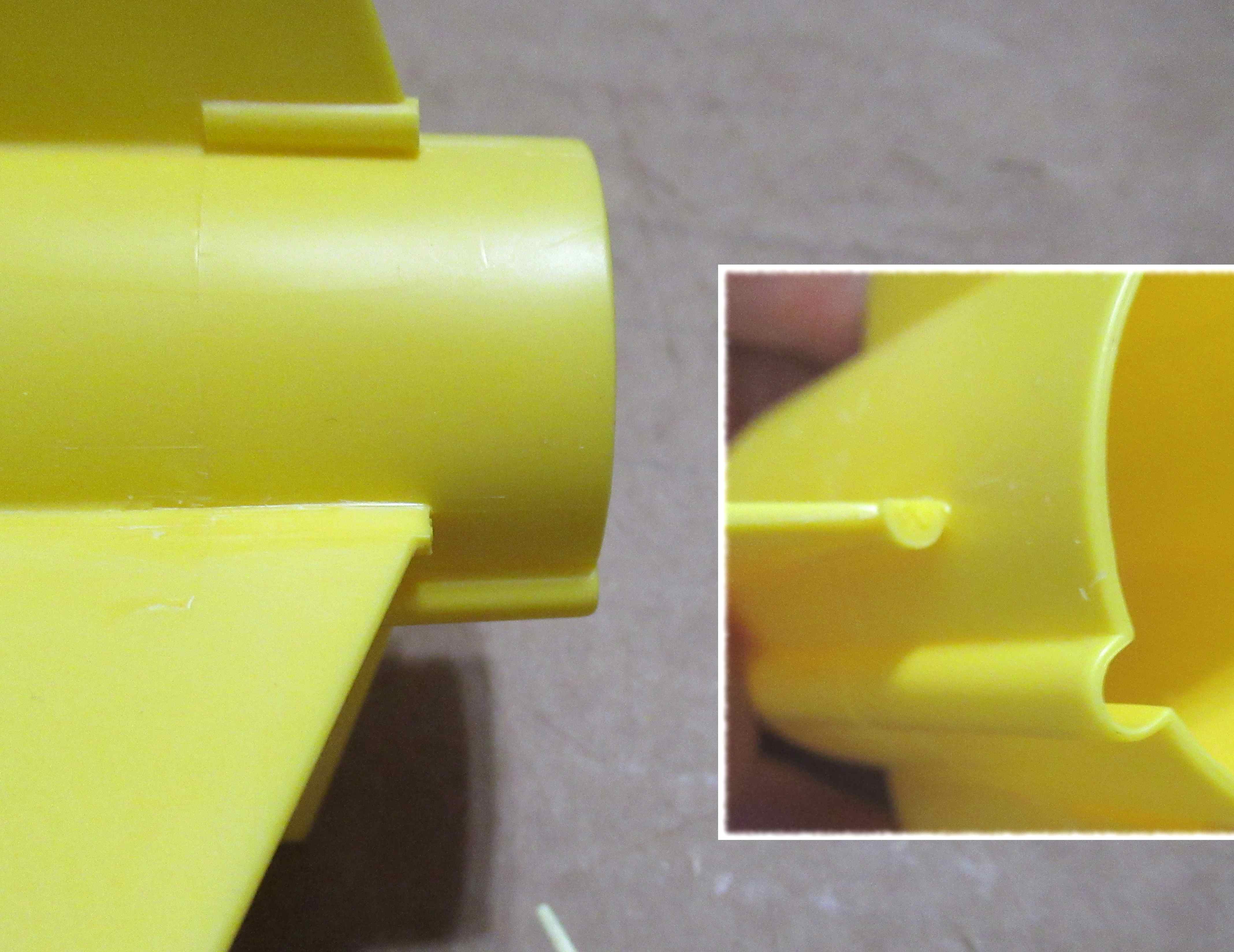
This was a bit scary to start - but that rod bump wouldn't allow the sticker to fit smooth into the root edge. Shaving down the rods ended up being easier than I thought.
I shaved off the bump with a new, sharp #11 blade.
I use #11 blades for delicate cuts like this. The majority of my build cuts are done with a break-off blade knife. 


You only have to shave down the rods on two fin faces. Check the kit face card picture for the two fins that have the (root edge fit) stickers.

The inset picture shows one half side from the back of the fin can. Try to get the surface as smooth as you can.
On two of the four Quest builds,
I had already painted the fin cans white. I'd recommend cutting down the rods first - then spray paint the fin cans white.

Here I painted first, then shaved down the rods. That cut them right down through the yellow plastic.


I had to go back and touchup with gloss white.

The sticker will cover most of the touchup area.

Thursday, May 19, 2022

Quest Falcon #Q1009 Build, Part 2, Parts


The Falcon now contains both a 24mm and 18mm engine mount.
Lots of engine versatility here.
Here's the fin can.
The "extension" is to the rear, towards the engine end. To the right is the sticker sheet showing the fin face.

If you are to assemble this model - 
This picture shows the orientation if the engine mount is to the left and the nose cone to the right. You might find yourself tempted to set the fin can going the other way with the extension facing the nose. I know I did. 

I started on the parachutes, four builds and four chutes.
After the reinforcement disks (rounded squares) are in place, I made the shroud line holes with my rotary punch. To make an easier punch, set some cardstock on the other side of the chute and punch through the plastic and the cardstock at the same time.

TIP: Stabbing the holes through the thin plastic with a pencil point could start a tear. Punching the holes gives you a cleaner edge round hole.

Thursday, June 25, 2020

Estes M.A.V. #7283, Build Part 4, Fin Can


The instructions show tube type plastic cement. I used brush-on liquid cement.

The fin can halves were pressed together dry.
The internal joints were brushed with the liquid cement while holding the joints closed and tight. Just the internal joints and at the top and bottom of the fin can got brushed on glue.


The fins slide into the bottom of the slot and are pressed up, locking them in place.
TIP: You really don't have to glue these fins in place. With the fins off you could easily fit this rocket in your range box. Slide in and lock the fins in place with the retaining ring at the flying field

On the left, the black ring isn't screwed all the way up yet. Notice the little bit of the slot still showing.

On the right, with the ring tight the fins are locked in place! They can't move up or down.
You could glue the fins in place but why? If a fin were to break, you've got a much easier fix.

Wednesday, June 24, 2020

Estes M.A.V. #7283, Build Part 3, More Interesting Things


Continued from the last post:

Here's the top of an engine sitting in the motor mount/fin can. Notice how it is centered, just inside the upper centering ring hole. The ejection charge would clear the plastic lip of the ring.


I did a dry fit of the fins.

Against a back light you can see the airfoil taper.

Here's the launch lug again.
The left side of the base is right down the seam of the wrap.
Usually on a factory installed wrap, the detail lines don't match. On this one - everything lines up!

It looks like the lug was glued on with a hot glue. There is a little clear glue squeezed out on each side.

Friday, December 27, 2019

Centuri Argus #KB-9, Build, Part 6, Prepping The Fin Can


The old Centuri instructions tell you to "Prepare the fin unit before sliding it down over the lower body tube." You are directed to use the "enclosed sandpaper" to smooth the inside edge of the fin unit.
I don't remember ever seeing sandpaper included in a Centuri kit. The New Way square tube kits include sandpaper.
There can be some rough molding flash on the inside lip of the fin can. This could scratch the tube if left on the inside.


Run your finger around the inside lip and you'll feel some slight molding "ribs". I used some 400 grit wrapped around an engine casing to smooth them.

The front end of the can wasn't even. The 220 grit block flattened it out. I followed with 400 grit.


The top of the molded in launch lug was cleaned up with a diamond needle file.

The Centuri instructions say to slide the fin can down from the top - all the way down to the bottom.

TIP: With a little wiggling, I was able to slide it on from the bottom up. This is a good thing, I'm going to paint the body tube gloss white. The fin can fit is tight and could scratch the paint if slid down from the top.

Centuri Argus #KB-9, Fin Can From Thingverse

In a blog comment, Metalhead 1986 let me know:
"For those with 3D printers, the fin can is available on Thingiverse."

To go to the web page: CLICK HERE
Thanks to Jack Hydrazine for all the hard work.

The webpage also listed all the models that used this fin unit:
ENERJET: 1340 Sounding Rocket, 1340/20 Sounding Rocket
CENTURI: Phoenix Bird, Argus, M.A.R.S. Project
ESTES: Longshot, Maniac, Challenger II, Eliminator, Eliminator XL

Saturday, September 28, 2019

Estes Solo #7288 Build, Part 3, Engine Mount & Fin Can

The fin can is interesting, there is no internal engine mount tubing. The top of the engine slips into a molded recessed ring at the top. A taller molded ring at the rear. The rear is threaded for the engine retaining ring.

The instructions show a tube of plastic cement used to glue the sides together. I held the sides together and brushed liquid cement on the inside joints.


I used Beacon Fabri-Tac glue on the root edge areas of the fins. Here I marked the root edge with a Sharpie to show where the glue was applied. The fins were slid into place.

More liquid cement was brushed onto the gap at the rear of the fin root edge. Let this glue dry before screwing on the engine retainer.


Here's the finished fin can. The fins with the glider attachment pins are on shown at the top.

As it is now, this fin can looks like the back end a sci-fi rocket.

Friday, March 8, 2019

Estes Black Brant II Kit #1958 Build, Part 11, Fin Gluing


TIP: Keep small parts in bags until they are ready for gluing on the model.
Anything that can fall on the floor or roll off your work table.
In this bag are four antennas (one extra) and the short 1/2" long launch lugs.


Just to check it, I wrapped the fin marking guide around the BT-55 main body tube. It was off by about 1/16".
Even without the nearly sanded off primer/filler, the fins would be a bit off  using this guide .
I ended up using another marking guide.


That small filler piece was formed even more. The sides were rounded to fit the curve of the slot running around the tail cone.


Some of the wood glue fillet ran into the slot.
Wood glue fillets (followed by Titebond No Run - No Drip) were used above the white tail cone.


Beacon Fabri-Tac was used on the rear of the fin where it contacts the tail cone. Fabri-Tac fillets followed.

Tuesday, January 29, 2019

Estes Vanguard Eagle, Kit # 2193, Part 4, Fin Can


The plastic fin can is made up of four side pieces.
The four fins are in halves, split right down the middle. (See the next picture.)
When all four sides are glued up it makes a very strong fin can.

Look close to the sides of the centering ring to see the ridges in the fin can piece. The centering rings glue into the ridges.


I applied Beacon Fabri-Tac glue inside the ridges and pressed the centering rings in.

When gluing the second, third and fourth sides on, wrapped rubber bands applied pressure to hold everything tight.

Notice the open halves of the fin.


The fin halves were gently opened and some liquid plastic cement brushed in.
Liquid cement dries fast so clothes pin clamps were quickly put on.


Three of the four sides were butted tight together. When the fourth side was pressed in, there was a slight gap. This will be filled before painting.

Thursday, April 5, 2018

Estes Saros, K-54 Build, Fin Can Build, Part 5, Lugs and Fin Plate


The instructions say to cut two 1/8" diameter launch lugs to 1/4" long.
That strikes me as pretty short. Any twisting when you slid the rocket down the rod and a lug could tear off.
I decided to go a bit longer at 3/8".

I buy launch lugs from Balsa Machining Service. They seem stiffer than the Estes kit lugs and don't crush when cut with a razor blade.

The short lugs were slipped over a Q-tip to get a coat of CWF and fill the lug seams.


The face card photo is probably a prototype build. The fin plates aren't molded into the plastic fin can. The plates look more like a chrome sticker with some black print.
My clone will be closer to this look.

Wednesday, April 4, 2018

Estes Saros, K-54 Build, Fin Can Build, Part 4, Engine Mount Assembly


Glue was applied to both rings and the outside BT-50 tube slid in place. After the tube is placed, wipe off the excess glue.

A glue fillet is placed around the base of the lower tapered ring.
The nozzle shroud is slid up from the bottom and into the glue. Wipe off any excess glue with a Q-tip forming a fillet.

A 1" long BT-50 coupler will join the fin can to the longer low tube.

Sand off the edge for an easier sip fit into the fin can.
TIP: These brown couplers seem to always have a tight fit. ALWAYS test fit before using any glue. Sand the outside until you have a easy slide dry fit.


A bead of glue was applied inside the upper edge of the short BT-50 tube.
The coupler was quickly slid into the tube up to the halfway mark.

Monday, April 2, 2018

Estes Saros, K-54 Build, Fin Can Build, Part 2, "Nested" Nozzle

The original kit had a plastic fin can. The rocket recovers low end down and would land on the plastic nozzle first. This clone will use a doubled, cardstock nozzle. Properly made it should be plenty strong on a hard landing.
I explained this 'Super Shroud" technique in an article published in the Apogee Peak Of Flight newsletter. To see it: CLICK HERE
The double nested card stock ends up very hard, almost like plastic.

Here's the two shroud prints, rolled and glued, nested one inside the other.
On the left notice the "step" of the inside shroud. The step also makes a tapered, wider glue area for adhesion to the inside smaller tube.

On the right side you can see the inside shroud overhanging the bottom of the outside shroud. This is a dry fit on the engine mount tube.


The low overhang is trimmed off using a single edge razor blade. Try for a clean cut. Any roughness will be sanded smooth in a moment.


On this model the bottom edge is open and exposed. If this was a transition adapter between two tubes you wouldn't want to treat the edge with CA. If the edge had a CA glue coat, white or yellow glue wouldn't soak in and adhere.

Just the edge got a wipe with medium CA. Now you can sand the wide end flat and even using a sanding block.

Sunday, April 1, 2018

Estes Saros, K-54 Build, Fin Can Build, Part 1, Parts


Here's the parts I put together for the fin can assembly:

From the bottom left going clockwise - 
The cardstock nozzle (pattern shown below)
1 3/8" long BT-50 segment
1" 50 sized coupler
Two 20/50 centering rings
20 sized engine block
BT-20 engine tube, 2 1/4" long.

The engine hook was not used. The engine will be friction fit.


The nozzle was formed from card stock using the Transition Tool from payloadbay.com
If you ever need a transition drawn for you, plug in the sizes needed and print!
The first diameter is .736", the outside diameter of the BT-20 engine tube.
The bottom of the nozzle bell looks close to 1" diameter, a guess on my part.
The length is right around .7" tall.


The fin and nozzle were re-drawn in Corel Draw.
I always print up extra transitions.

I'll be making a doubled nesting or "super shroud". Consider this model will land nozzle down, you'll want it to be strong.

Wednesday, February 21, 2018

ASP D Region Tomahawk Build, Part 16, Fin Plate Setting and Streamer


The backs of the card stock fin plates were sprayed with 3M 77 adhesive spray.
Here's how the plates fit around the curve of the tube and with the folds tucked into the fin root edges.

The great thing - the fin plates covered the bad and touched up mask lines.


A Q-tip was used to gently press the fold into the root edge. You won't scratch the print using a soft burnisher.
There is a 1/8" wide aluminum band at the rear edge of the body tube. Instead of masking and painting, a strip of Trim Monokote was cut and applied. It took a few tries to tuck it into the fin base but it was easier than masking.


The streamer is thick yellow plastic, 3" wide X 24" long.
The streamer is taped to the shock cord, 1" from the end of the streamer. Fold the end over the shock cord and tape it again.