Thursday, June 30, 2022

Dean Henson's Centuri Bulldog


From the Model Rocket Fanatics page, 
Dean Henson Posted:

"I’ve just completed my scratch-built Bulldog AGM 83 A and I thought some may enjoy seeing it. It’s a clone of an old Centuri kit that you don’t see very often. I did take liberties in creating an “eye” for the missile, so not wholly “as-in-reality,” but pretty cool in my estimation, nonetheless. I hope that you’ll still find it interesting!"


Here's the first listing from the 1982 Centuri catalog:

By the early 1980s, newer Centuri designs were using Estes parts. This rocket had a diameter of 2.217" or a BT-70. Quite a large model to use 18mm motors.


Check out the lens set into the nose cone! That wasn't part of the original kit - 
The Centuri kit nose cone had an extension card stock shroud like some of the Launch Pad kits.

To see the Centuri kit instructions, go to Jim Zs:

Wednesday, June 29, 2022

Out Of Round Tubes? Part 2


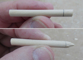
The middle of the tubes are rounder now. But, the last inches on each end are still a bit ovaled.  
Lightly squeeze the ends round. 
Hold the tube end round and again hold over the slow boiling water for a few seconds - Until you can feel the tube softening. 
Lift away from the steam while still holding the tube end round. When the tube cools it should hold the new round shape.


The absorbed steam might slightly raise a spiral seam on the outside of the tube.

Slide the couple back into the tube.
Burnish over the tube and seam with a flat burnisher.


On the left is the before -

And the same tubes after steaming and reforming. Quite a difference!


This doesn't always work! 
Like I mentioned before, if you can see cracks or the crease is sharp - You are better off replacing the tubes.

Tuesday, June 28, 2022

Out Of Round Tubes? Part 1

Why take the time to fix a tube? 
This was an older, OOP kit. The older brown tubes feel stronger, they might have a smaller percentage of recycled fibers. I don't know! I thought it would be worth a try. 
Maybe you can fix an older out-of-round tube and assemble the kit using the original parts.
    
Oh Boy! We've all been there - 
You buy a kit through Ebay. It is listed as sealed.
The bag is opened. 
All the parts are there, including some out of round tubes! 

These tubes are soft ovaled - not sharply creased or bent.
I wouldn't try to save a tube that had a crease, where you could see cracks in the tube. If the tube is folded, the fibers are broken.


The Kraft tubes have have some "memory" if the fibers aren't broken.

I had a long 50 tube size coupler.
I didn't want a tight fit inside the BT-50 tubes.
I sanded the coupler sides a bit smaller using 220 grit on a block.


The coupler was slid into the tube. The coupler extended beyond the end of the tube.

Some water was heated in a pan to a low boil.
Notice the steam.

Hold the tube about 2" above the lip of the pan.
Some of the steam will be absorbed into the tube. You don't want the tube wet! Just a slightly damp.

The coupler slid in the ovaled tube helps force it back to a rounder shape.
More tomorrow:
Monday, June 27, 2022

Rob Caswell's Jetliner

I've shown Rob Caswell's work before! This is a great kitbash of the Estes Jetliner.
It reminds me a little of the Shrox Lexxjet.


"I still need to throw a final clear coat on, but otherwise my modified Jetliner is done. I really should think up a new name for it, since 90% of the Jetliner’s parts were replaced and/or rekajiggered. And yes, it’s highly inspired by the Honda HA-420. Decals are my own creation… and “RADSA” is the “Rob and Deb Space Agency”: our own logo and name for our collective flying model works."


"Based on reviews I read, I upgraded the Estes Jetliner design from a 13mm to 18mm design as many had complained it was underpowered. In its one test flight, with a B6-4, it flew rock solid."


Here's how the original Estes kit looked - 
I like Rob's version better! Custom decals, details and an upgrade to 18mm motors.

Sunday, June 26, 2022

Smooth Launch Lug Fillets?

Fin fillets are pretty easy. 
Deep launch lug glue fillets are another story.
   
Here's how the first wood glue pass looks after it has dried. You can see the air bubbles at the root.


A second fillet pass and the bubbles are getting smaller.


After that fillet has dried - 
Lightly run the back of a knife blade over the fillet and you might feel some dips. Add another fillet.
After two fillets of wood glue I switch over to the Titebond Quick & Thick glue. It is 3x thicker than standard Titebond original. There's still a small bubble hole - Add another layer of glue. Every additional layer uses less glue.

I roll off the ends with a Q-tip. This tapers the ends at the top and bottom of the lugs.


Here's a smooth fillet on my Orbital Transport Laboratory build.

When white undercoats are first set down you might notice some ridges on the sides of the fillets. After the paint dries, lightly sand the glue ridges down. 

On a model like the Orbital Transport I wouldn't even try to apply a glue fillet in the wing/tube joint. 
You would have to apply too many layers of glue to fill in all the bubbles in the fillet! That's a lot of extra weight on a glider. 
 

Saturday, June 25, 2022

Odd'l Rockets F-18 Hornet Development & Build, Finished


This back shot better shows the black inside rudder wall.

The engine hook was moved to the center top to make engine install and removal easier.


The underside showing the dual jet tubes and new 3D missiles. 

Visually there is a lot going on. 


The nose with all the decals applied.

Friday, June 24, 2022

Odd'l Rockets F-18 Hornet Development & Build, Part 10, Decals & Canopy Gluing

The cockpit decal is placed first. 
The front end is placed 3/16" back from the front edge of the body tube.

Dry set the stripes to get an idea of the angle needed.
The top ends can set over the black in the cockpit decal a bit. The underside will cross over the decal line on the other side.
After the decals are almost dry
Use a single edge razor blade to cut through both decal strips.
Use only enough pressure to cut through the thin decals - don't cut into the paint.

Lift the top decal and remove the overhang. Remove the overhang from the lower decal. Wet the surface and reset the strip ends down.

Now the canopy can be glued in place.
Do a dry fit to see how much border spacing is around the cockpit decal.
Hold the canopy in place when applying the glue with a toothpick. Glue a small area of the canopy at a time.
Squeeze out a drop of Medium CA Super Glue onto a scrap piece of cardboard. Dip a toothpick into the CA glue. Drag the small drop of CA glue around the edge of the cockpit edge.
Continue until the contact edge around the entire canopy has had glue applied.


The rear of the jet engines gets a wrap around decal.
Start the decal placement at the center point where the tubes touch. Roll the decal around the tube.

Thursday, June 23, 2022

Odd'l Rockets F-18 Hornet Development & Build, Part 9, Paint, Missiles & Trim


The entire model gets spray painted a light gray.

No masking - unless you want the inside surfaces of the rudder fins to be black. A work-around is shown below.


This shows the evolution of the wing missiles.
On the left is an original Centuri Fighter Fleet missile. There is a molding bubble in the nose.

On the right is the new 3D printed small nose cone and fin can slipped into a 1/8" diameter launch lug segment. 
Thanks to David Koo of reallykoostuff.com for the 3D prints.
I used my "go-to" black vinyl for the inside rudder surfaces. The peel and stick black vinyl is self adhesive Chalkboard Contact Paper.

Cut out the decals with the backing paper still on - don't soak the decal yet. Trace around the dry decal and cut inside the pencil lines to leave a gray paint border when centered on the rudder face. 
The bottom edge of the vinyl piece goes into the fin root edge.


Here's the black vinyl piece on the inside face of the rudder.

This is an earlier build before I had the 3D printed missiles.

Wednesday, June 22, 2022

Odd'l Rockets F-18 Hornet Development & Build, Part 8, Canopy Fitting

Take it slow when working with vacuform pieces. 
This applies to the vacuform parts in the Estes Saturn V, Saturn 1B and the Odd'l Fighter Jet canopies. An extra 10 minutes of careful cutting and sanding will lead to a great fit and strong body tube bond.
   
The border of the canopy has to be cut off before fitting to the tube.
To better see the recessed edge, draw around the base with a ultra fine point Sharpie or ball point pen.

With a new sharp blade - 
SCORE around the line. Don't try to cut through with a single pass.

With your score cut halfway through the plastic, flex the plastic down the cut line until the border plastic breaks off.

At the lower right, it says "Score and break lines." Note the lines at all four corners. 
It helps to cut these outside lines to as you are flexing to break the pen line edges.
This illustration is from the kit instructions.
Set some fine sandpaper around the BT-50H body tube. Note the pen lines are still visible. These will end up being sanding off.

Go back and forth in a straight line down the tube over the sandpaper.
 
Here you can see the pen marked edges getting very thin and starting to come off. About the time all the pen ink is gone you should be getting a good fit on the body tube.

Don't glue the canopy on yet. 
It will be glued on after spray painting and decals are applied.

Tuesday, June 21, 2022

Odd'l Rockets F-18 Hornet Development & Build, Part 7, Nose Cone Tries?


At first, I tried to make a nose cone where the tip dropped down like the real jet.


The shoulder base was sanded at an angle.
With the new shoulder it required the inset base to be tapered.  


Here's a normal nose cone fit.
And below with the dropped tip.

This nose cone idea was cut. 
It took too much work to make it fit well. I had to assume some builders wouldn't be happy with the end result.

After A, B and C engine test flights I switched over to a plastic nose cone.

The original balsa nose cone, nose weight washers and screw eye were weighed. 
The plastic nose cone was weighed and clay added to get it up to the previous stable flight weight. 

Someone suggested to have the drop nose cones 3D printed. It's a good idea, but would really raise the price of the kit.

Monday, June 20, 2022

Odd'l Rockets F-18 Hornet Development & Build, Part 6, Those First Missiles


The first batches of F-16 kits had launch lugs for "missiles" a little like the Quest AS-1 Fighter Escort design. 
The F-104 Starfighter has carved dowel wing tanks.

The F-18 Hornet missiles started as dowels with a rough carved tip.


Draw a pencil line for a taper base.
Rough carve the tip.

Smooth out the tip by spinning it against sandpaper on a block.


And here's how the first test flight models turned out. No filler, paint or decals yet.

I'll show how the canopy is fitted and adhered in an upcoming post.


At this stage a dozen test launches were made using A8-3, B6-4 and C6-5 motors.

Sunday, June 19, 2022

Odd'l Rockets F-18 Hornet Development & Build, Part 5, Gluing On The Jet Engines


The first jet engine tubes I glued on didn't give a good visual fit. They were first glued away from the center line and ended up with a space between them.
This was a test build so I wasn't too concerned about how the assembled model looked. The tubes were cut off and new ones placed.


Here's a show model with one tube glued in place.
The cut notch slot allows the jet tubes to overhang and wrap under the BT-50H tube.


From the rear - 
Notice the engine hook was moved to the top to allow easier engine insert.


With the jet tubes to the center I have room to glue (and hide) the launch lug.

At the top is an early version of a dowel missile before they were 3D printed.

Saturday, June 18, 2022

Odd'l Rockets F-18 Hornet Development & Build, Part 4, Engine Mount & Jet Engines


The engine mount is standard with the Kevlar line retained under the top bend of the engine hook.

The engine tube is an Odd'l Rockets heavy wall BT-20H, stronger than a standard BT-20.
A tube marking and cutting template is supplied with the kit. You will be removing a long rectangle piece so the BT-5 tube can overhang the end of the BT-50H main airframe tube.

Wrap and tape the paper template around the BT-5 tube. Punch small holes with a pin down the cut lines. Remove the template and connect the punched dots with a pencil line.


With a new, sharp blade -
Cut the end first.
Then cut the long side lines. You'll find it easier to cut a straight line using a aluminum angle for a knife guide.


Here's what you should end up with.
Notice there is some rough edges.


Careful sanding with a block will clean up and straighten out the cut lines.

Friday, June 17, 2022

Odd'l Rockets F-18 Hornet Development & Build, Part 3, Wings & Stabilizers

The wings, stabilizers and rudders stayed pretty much the same from the "naked" test models through the bagged kits.
The wings are two piece.
Both the wings and forward fairings are glued together. It helps to set them against a straightedge while the glue dries. 
You can also set a medium weight (like a small paint bottle) over the joint to even things up.


Here's how the wings and stabilizers set on the body tube, directly opposite each other.

For a stable model, the wings are moved back - no space between the front tip of the stabilizer and the rear edge of the wing.


The root edges of the two rudders are sanded at an angle for a better glued fit on the tops of the stabilizers.
The two rudder root edges should "mirror" each other.
Here's how they glue onto the model. The root edge of the rudders are against the root edge of the stabilizers and touch the body tube.

This picture shows the engine mount from the later "show" model build. The test models had the engine mount with the engine hook at the bottom. This was changed to the top when I found it a bit difficult to remove the engine with the two jet engines glued onto the bottom.