Showing posts with label Ejection Venting. Show all posts

Thursday, January 2, 2025

Estes Black Star Voyager Build, Part 3, Engine Mount


Here's the finished mount with the notched centering ring glued up against the black retainer ring. The flat face of the ring is spaced 1/2" from the rear of the engine tube.


Again, I used my aluminum angle to glue on the upper (Part L) tube in line with the engine mount.
Jumping ahead:
The base of the adapter has holes cut to allow the ejection charge gases to pass through and deploy the parachute. I don't remember ever seeing ejection holes made through a plastic adapter.

Pencil mark the hole positions before drilling. The four holes should be around 1/8" diameter.

Friday, July 8, 2022

Estes Blackhawk #2053 Build, Part 7, Gluing The Mount & Tubes


Again I used some 220 grit wrapped around a casing to open up the side tube hole.


A dry fit and tracing around the tube joint with pencil. 

A glue line was set on the pencil line and the tubes joined. 
Double check the alignment before the glue starts to set up.


Like on the old Estes Trident -
TIP: Be sure to add some heavy fillets that won't blow out at ejection.

Thursday, July 7, 2022

Estes Blackhawk #2053 Build, Part 6, A Third Vent Tube!


This instruction drawing better shows the assembly.
The ejection charge goes up, makes left turn then goes up again. Remeber, there's a bulkhead in the larger tube that directs the ejection charge up. 
That Centuri rear eject would have been easier.


Here's the final vertical tube, a BT-50.
This one also gets a reinforcement coupler and another cut hole.

I'm marking the dowel to apply glue inside the tube. The tubes above give me a height reference.


The yellow tube pushes in the coupler.
The yellow tube also sets the cardstock bulkhead. 


The final circle cut!

Tape and mark with the guide wrap. Pencil trace and another new #11 blade!

Wednesday, July 6, 2022

Estes Blackhawk #2053 Build, Part 5, Gluing Vent Tubes & Interior Supports


With the engine mount tube straight in the vent tube - 
I traced around the joint for glue placement.

A line of glue was placed around the pencil line and the two tubes joined.


After that dried,
Both of the cardstock central plates is set next to the engine tube. (See next picture.)

Mark both sides for the the retainer ring (or tape).


Cut a slight notch in both of the central plates.
Couldn't this have been included in the die-cuts?

This is in the instructions, to cut out an area to allow for the retainer ring.

Tuesday, July 5, 2022

Estes Blackhawk #2053 Build, Part 4, Cutting The Vent Holes

Hoo Boy! This is a tough cut to make. I wouldn't usually put in a new #11 blade, but for this cut it is needed. 
The guide is wrapped and taped so it can't move.
Score the oval cut then remove the guide.

Cut, cut and cut some more. Going through the old style fish paper coupler takes many passes.
 

On the left side picture you can see the two layers of tube and coupler. That tube cut reminds me of Pac Man.

My scanned cutting guide must have been small. The engine mount tube wouldn't slide in.


I wrapped some 220 grit around an used engine casing and rotated it in the side vent hole.

Right side picture:
Looking up the engine mount from the rear.
I've marked with a pencil where the fit was tight and needed a bit more sanding for a friction fit without any tube distortion.

Monday, July 4, 2022

Estes Blackhawk #2053 Build, Part 3, Engine Mount & Ejection Venting

The vertical engine mount tube:
The lower central tube is the engine mount.
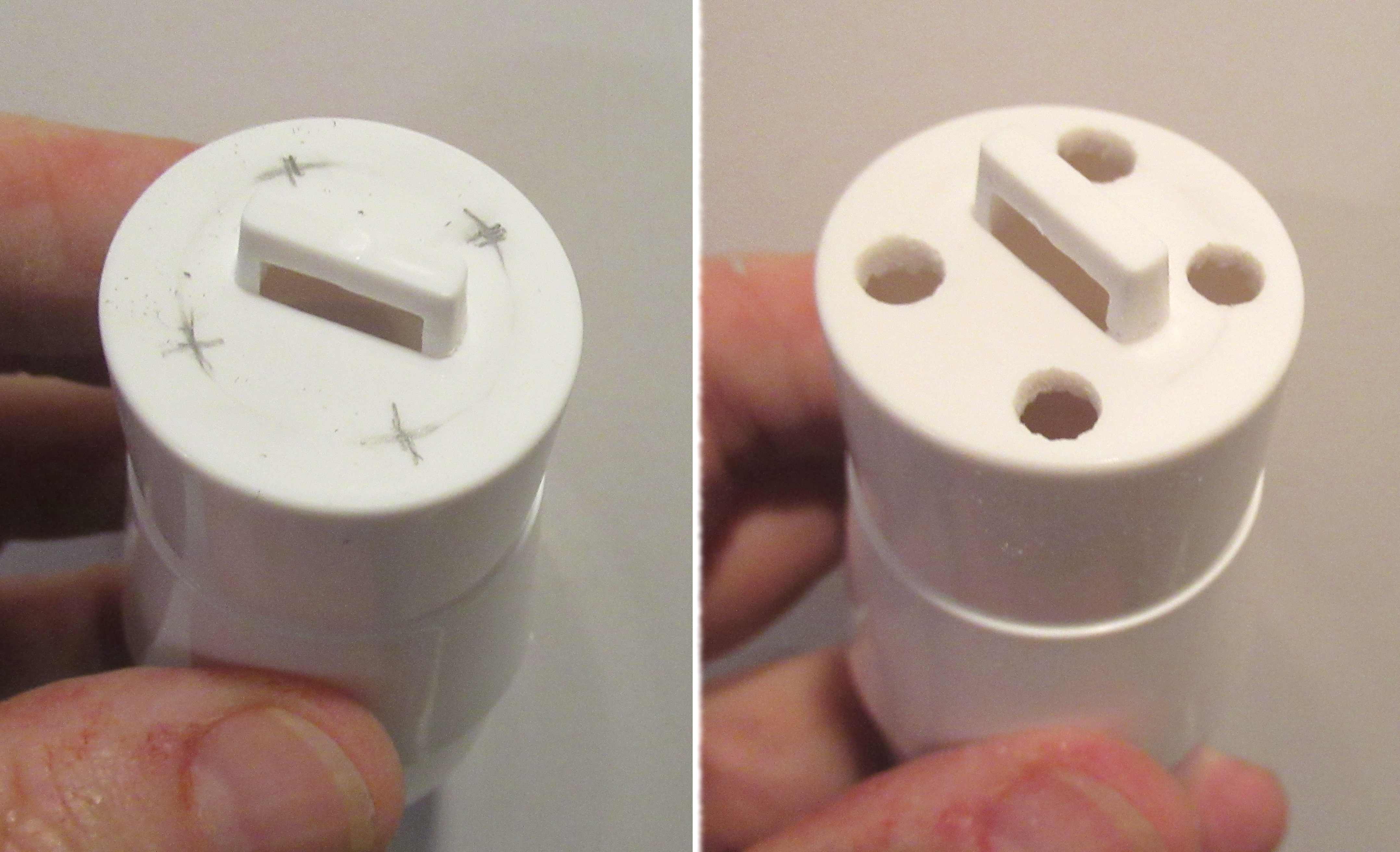
I had to make a marking guide as my scanned copy didn't match up.

There wasn't a Mylar engine hook retaining ring in the kit bag so I did my standard electrical tape wrap.

For a while, some Estes kits didn't include an engine block. I incorrectly used the only engine block in the kit when it should have gone into another tube vent. It's okay, I have plenty of extra engine blocks. 
EDIT: Good thing I used the engine block here - The end of the BT-20 tube takes a beating when getting a good fit in the cut circle on the side tube.
 
Moving to the horizontal vent tube:

A shorter vent tube goes to the left off the engine mount.
A reinforcement ring (gray fish paper coupler) goes 5/16" into the vent tube. 
You will be cutting a circular vent hole through the BT-20 tube and this interior reinforcement coupler - a thick, difficult circle to cut out.  


A white cardstock bulkhead is pressed down onto the edge of the reinforcement coupler.

I peeled the inside layers out of a thicker engine block. This glues in resting on top of the bulkhead.