Showing posts with label Joining Tubes. Show all posts

Monday, August 24, 2026

Estes Cosmic Interceptor Build, Part 9, Joining The Tubes

The picture on the left shows a dry fit of the two tubes joined by the coupler.
Note the pencil reference line, drawn where the tube fit is best. There are still small gaps.

On the right is a better fit, sanding the tube ends square with a sanding block.


The coupler ends are beveled for an easier slip fit in the tubes.

The bevel also lets the glue pool up at the edge a bit.

If you use yellow or white glue, don't use too much. The dried glue could shrink the tube.


I'd recommend using epoxy for couplers and engine mounts. Epoxy won't lock up like yellow or white glue can.

After sliding the two tubes together, I use a burnisher to mold any raised areas.

CWF is brushed on the seam joint and sanded.

On the right you can see the high and low spots after sanding.

Sunday, July 26, 2026

Estes Mini Scale Combo Pak, #0874, Tomahawk & Exocet, Build, Part 5, Joining Tubes


Always round over the corner ends of couplers for a smoother slide in the tubes.

This coupler is marked 3/8" from the ends with a center line.


The coupler is glued into the longer tube.

The shorter tube is glued on top, over the coupler.


The joint seam is filled with thinned CWF.
Dip a knife tip into the CWF, drag the filler bead around the seam.


Sand the joint with 400 grit on a sanding block.

Friday, November 8, 2024

Enerjet by Aerotech Strong Arm Build, Part 9, Filling The Tube Joint


Here's the tubes together, the coupler inside glued together using 15 minute epoxy.
The pencil lines are lined up before the glue sets up.


Most of the joint gap was first filled with CWF, the excess smoothed out using a single edge razor blade.

The picture shows the joint after the CWF was sanded to surface.


The high spots end up fuzzy after sanding.

I wipe on some medium CA Super Glue using a Q-tip applicator.

After it dries, sand using 400 grit on a block.


A final fill is a shot of filler/primer and sanding with 400 grit.

Taking these extra steps, you shouldn't see the tube joint seam on the finished model.

Tuesday, November 5, 2024

Enerjet by Aerotech Strong Arm Build, Part 6, Fit & Joining Two Tubes


On the left are the two tubes slid together using the coupler inside. No glue yet.

On the right is after sanding the tube ends square, the sanding shown below in the left side picture. Again, no glue yet.
Square up both tubes with a sanding block with 220 grit.

Slide the tubes together using no glue over the inside coupler.
Rotate the upper tube until you get the best, tightest join of the two tube ends.
Mark that best joint with a pencil line. When glue is applied, line up the pencil lines.

Having a tighter joint of the two tube ends will make it easier to fill the seam. 
The seam fill is coming in a few posts.

Saturday, October 12, 2024

Estes Star Stryker Build, #3206, Part 4, Joining Tubes & Fin Marking - Gotcha!


I sand the ends of the clear retainer ring with 400 grit to clean up the edges.
Here's the yellow coupler / engine block.
A line of glue is set inside the tube and the block is slid in until it rests against the top ben of the hook. 

Before gluing the long upper tube over the coupler - 
Slide the tube over the coupler (dry). Turn the tube until you get the best match of the two tube ends. Mark the position with pencil. 
Set a line of glue in the upper tube - slide over the coupler and turn so the pencil marks line up.

GOTCHA: The tube marking guide is printed a little wide to fit over the engine hook and retainer ring.
I marked the tube then rotated the guide to check the fin spacing against the next set of marks. It was off no matter how many times I turned the paper guide.

I went to payloadbay.com and printed off a new five fin marking guide. On the right you can see the difference between the two guides. The payloadbay.com guide is on the left.


The payloadbay.com marking guide was printed to fit a BT-20 tube.
I wrapped it above the engine hook and marked for the fins. Extend the marks down the tube.

Friday, August 12, 2022

Estes Super Orbital Transport Build, Kit #7314, Part 17, Joining The Tubes & Filling The Seam

The two BT-55 tubes are joined by a red coupler.
Before gluing - 
TIP: Do a dry test fit. Glue the red coupler into the lower tube. Slide on the upper tube (dry, no glue) and turn the upper tube to find the position of the best fit, making sure the tubes are in line. Mark this position with a pencil line over both tubes. Let the lower half coupler glue dry. Apply glue inside the upper tube. Slide on the upper tube and rotate to align the best fit pencil marks.


While the glue is still wet, 
Use your burnisher to mold and even up the joint edges. Let dry.

The tube seam is filled much like filling balsa.
First use CWF to do the bulk of the filling.


After sanding the CWF, you may have roughed up the tube.


A wipe of medium CA glue will harden up the edges for smooth sanding. 


Next up is a shot of filler/primer to fill in any remaining joint seam.

The launch lug and tip of of the forward wing strake is taped off from any filler/primer overspray.


Here's the seam after filling and sanding.
It will be barely noticeable after the gloss white is sprayed.

Tuesday, April 5, 2022

Estes EAC Firecat #0821, Build, Part 3, Closing The BT-48 Tube Joint


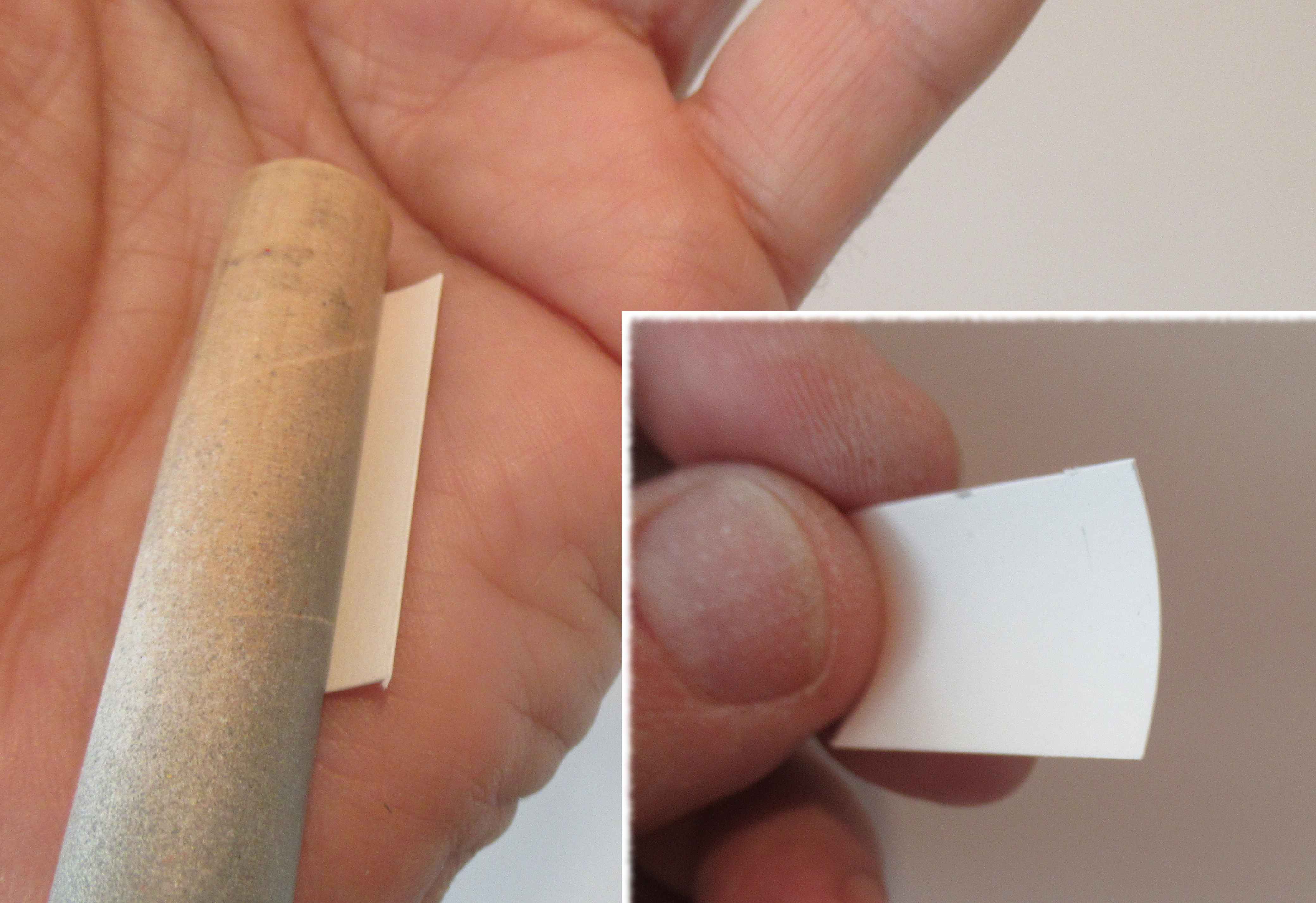
You'll need an interior patch to hold the butted joint seam on the BT-48 tube.
Cut a piece of cardstock about 1/2" wide and 1/4" longer than your body tube.

Pre-curve the piece in your palm using a rolling dowel until you get an arc as shown in the inset picture.
I used a thin coat of wood glue spread evenly over the entire piece.

Press in place centered over the joint. Use the dowel to apply pressure over the patch piece.

After it dries, sand the overhang off using a sanding block until the patch is even with the ends of the body tube.

When you are stuck without a proper part - 
Using this method, you can make couplers to join segments of body tubes.

To smooth out the joint,
Apply a small line of glue the last 3/8" on both sides. 
Wipe off the excess with a fingertip then immediately burnish and roll over the seam with a smooth pen barrel. Pressing the loose fibers into the glue should smooth out the cut. 
The ends will be exposed on the finished model.

Monday, March 29, 2021

TLP Hawk Build, Part 3, Engine Mount & Tube Fitting


The engine mount is pretty standard, designed for 24mm motors.

The engine hook retention is a wrap of black electrical tape.
With the coupler slid in place with no glue,
you can see the tubes weren't cut flat.

On the right is the tubes after sanding the ends square with a block.
TIP: Note the pencil lines. I marked the best fit after rotating the tubes. The pencil lines give me a reference when gluing them up.


Larger tubes are hard to cut clean even for a vendor.
Be sure to square them up with a sanding block with 220 grit sandpaper.


TIP: Bevel the ends of the coupler for an easier fit. Bevels also prevent the inside tube ends from peeling up.

Friday, April 12, 2019

Quest AS-1 Escort Build, Part 8, Fin Fill and Tube Gluing


The front edge of the two piece fins have a visible break.
Some CWF is set on the seam.


The inset picture shows sandpaper wrapped around a Q-tip stick.
This was used to round off the filler corner.
On the left is after the filler/primer was sanded down.


GOTCHA: The instructions say to mark the center tube at 1/4" and 4" from the rear for applying the glue line. The glue area should really be at 1/8" and 5".
For easier alignment, extend the centerline mark onto the engine mount tube.


The center engine tube is glue to the inside top of the rear tube.
Use your centerline marks to place the tubes in line. Double check the rear to be sure everything is centered.

Friday, March 22, 2019

Custom SLV Build #10044, Part 6, Upper Shroud & Tube Gluing


On the left I'm rolling off the inside burrs so the ring will slide over the BT-20 a little easier.

On the right are both 20/50 rings stacked and glued even with the top of the second upper BT-20 tube. 
The instructions say to apply a ring of glue 3/4" from the bottom of the lower ring. A dry fit showed the glue line should go a little below that. Dry fit the shroud and trace the low edge with a pencil to find the line.
Note there is very little glue where the shroud edges will make contact.


TIP: Before gluing any two tubes together with a coupler, sand the ends flat and do a dry fit. You might be surprised how many kit tubes are not cleanly cut.


After the tubes were joined the assembly got a shot of filler primer and fine sanding. There were some high areas especially around the seam joints.

Wednesday, January 16, 2019

OR Spaced Needle Build, Part 3, Gluing The Tubes Together

This post shows one way to glue together two tubes.
This didn't work for the first build of the Spaced Needle design, the model ended up too long to easily transport without damage.
The next post will show how to make a coupler so the model will break at the mid point.


Before gluing together any two tubes, roll over the inside taking down any burrs left from when the tubes were cut. It doesn't take a lot of pressure, don't distort the tube.
TIP: Before you glue two tubes together, think ahead. Have a clear, clean flat surface to roll the tubes over and insure they are straight. This is a tall model and will require a pretty big area.

A nice bead of glue was set inside the low tube.

The coupler (with Kevlar line tied and attached) was pressed in halfway.
While pushing in the coupler, try to turn it so the glue is spread out evenly.


Drop the long Kevlar line into the upper tube.

Place a line of glue inside the upper tube. Push the coupler in and turn. Don't let the Kevlar get caught in the joint.


The two tubes are rolled on a flat surface, here I'm using a counter top.

Plan ahead - Gluing two tubes should be done fairly quickly while the glue is still pliable, before it sets up.

Friday, May 11, 2018

Estes Mini A Heli #007272, Build, Part 14, Vent Slots, Tubes and Fins


Here's all three sides of the helicopter blades - top, back of the top and low end.


The inside and outside of the vent slots got a wipe of medium CA to strengthen them, especially at the corners. Light sanding to smooth the surface followed after it dried.


TIP: The two tubes were glued together using an aluminum angle. This helps keep them straight and is better than trying to roll them over a flat surface.


I used a Q-tip to apply a bead of glue for the engine block.
TIP: I marked the glue distance on the Q-tip with a fingernail. You can see the depression near my fingers in the upper picture.


The fins are glued on 1/2" from the end of the body tube. This 1/2" open tube area allows you to use a wrap of tape for engine retention, no engine hook.

The small, tapered launch lugs were glued and aligned. The low lug glues to the fin root edge.

Thursday, January 4, 2018

Model Minutes Leduc 22 Build, Part 5, Central Tube and Coupler


"General instructions Photography may lightly differ". (Yep, they typed "lightly differ".)
The central tube picture was different than the center tube included in the kit. The tube picture was from a different model.

Even the long central tube can be formed in the palm of your hand. Do one side then flip the card stock over and form the other side.

Be sure the end of the dowel is rounded, otherwise you might get some scarring that could show through at the tube mid-point after it is rolled.
The outside tube coupler was too loose on the lower T1 and upper T3 sections.
NOTE: To the left of the T3 mark is the upper centering ring location. Later in the build I glued the rings right between those lines.

I cut another strip of 110 lb. card stock and rolled a second, tighter coupler.
NOTE: The replacement coupler wrap I made was the exact length of the kit supplied piece. Notice it is set right to the placement line on the lower tube.

Why bring these printed placement marks up now?
I want to be sure alignment would be correct later on, all the lengths and part positions should be correct for the final assemblies. You'll see what happened in future posts.

Friday, June 17, 2016

Estes Interceptor Build #1250, Part 4, Tube Fix


The crimped tube was cut in two at the center of the bent area.
The black coupler seemed loose so a wrap of copy paper was glued over the outside to widen the O.D.

Note the pencil mark to align the tube halves and crimped area.


White glue was used. Enough glue was used so the tubes were pliable.
While the glue was drying a Sharpie was rolled over the seam and crimp to mold it flat and even. This makes for less to fill later on.