Showing posts with label Tail Cone. Show all posts

Thursday, June 11, 2026

Estes Sandpiper, Kit #1389, Part 3, Tail Cone


Payloadbay.com is down right now, that's usually my source for cardstock reducers and tail cones.

I did my best to size the kit pattern sheet (CLICK HERE) but there was no 1" reference in the image.

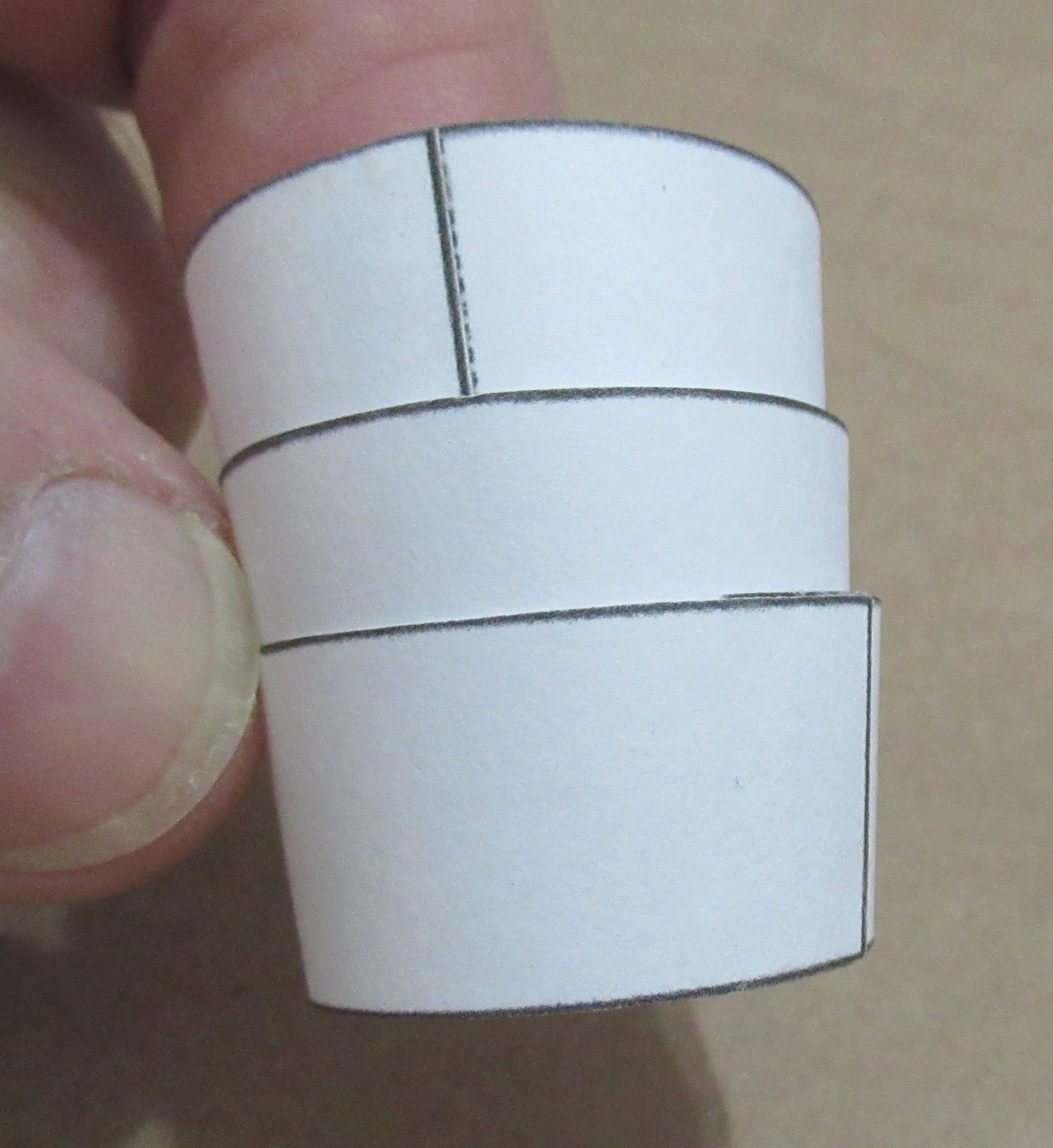
Crossing my fingers, I test fitted the shroud dry and marked the overlap line. In the picture, I'm burnishing down the glue tab. 

I'm using a heavy wall BT-50 and a standard BT-20 engine mount tube.
This will require some fitting, the heavy wall BT-50 has a slightly larger diameter over a standard BT-50.

The engine mount was glued in place with the lower centering ring extended out the back, about 1/16". This picture shows the assembly upside down.

To fit the imperfect shroud, I had to use some paper wraps. Two 20 lb. copy paper strips gave a good friction fit.


Light glue was applied and the shroud slipped in place.

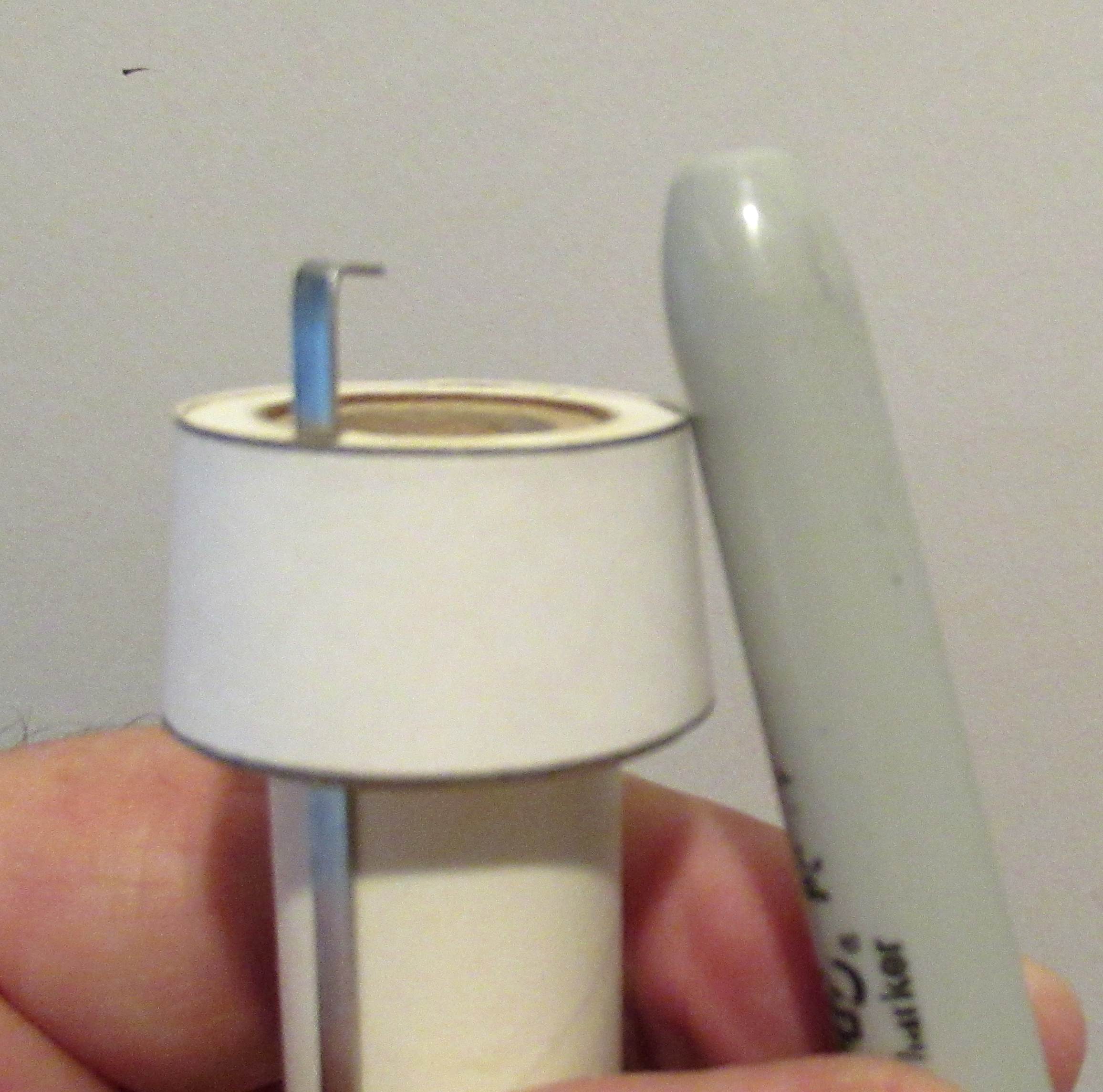
Before the glue sets up, you can do some "molding" of the still wet shroud edges. I'm using the smooth barrel of a Sharpie pen to press the shroud edge against the body tubes.

Saturday, March 28, 2026

Estes Mini Arcas, #2441, Part 5, Tail Cone Fix


Next time you make a tail cone, try placing the glue inside the end, opposite the glue tab.
I decided to make a double layer "super shroud". This makes a much stronger piece.
For more detail, I wrote an article for the Apogee Peak Of Flight newsletter: CLICK HERE

Notice the lower step inside the cone in the right side pic.


Glue one cone inside other.
Let dry with a coupler inside (don't glue the coupler in) to maintain the round shape.
After all is dry,
Cut off the upper overhang using the ridge as a guide for a razor blade.

Sand the upper side square using a sanding block with 400 grit.

Friday, March 27, 2026

Estes Mini Arcas, #2441, Part 4, Tail Cone Fix - Gotcha!


After forming too many shrouds printed from the scanned kit tail cone,
I thought I'd try the provided kit shroud.
GOTCHA: The kit shroud fit like my scanned cardstock ones did - 
It fits the BT-5 but was small on the BT-20 top end.


So - off to payloadbay.com and their transitions tool.

Four more were printed and cut out.

Notice the picture on the left - 
Run a fingertip over the curved sides, you'll feel some very subtle raised areas. With 400 grit, sand and round them down. This removes the high spots and makes a better fit at the base of the BT-20.


Four cardstock tail cones were formed with a clean dowel in the heel of my left hand. Check the last post picture.

Thursday, March 26, 2026

Estes Mini Arcas, #2441, Part 3, Tail Cone Problems


Cut the flat sides with a ruler and sharp knife. 
Cut the curves with scissors.


I make a smooth curve by rolling a dowel in an arc pressed against the soft heel of your hand. 

It take very little glue to join the ends.
With the printed edge lines lined up, I held the shroud closed using smooth faced tweezers.
 
Here's where I ran into problems.
The bottom fits the BT-5, but the wider end doesn't match the diameter of the BT-20!

I made another tail cone with a slightly wider top. 
It was still too small!


These two shown above aren't the kit supplied tail cone. The kit shroud was scanned and some extras were printed up on 110 lb. stock. There doesn't seem to be any difference in size between the kit shroud and what I printed. I was saving the kit tail cone for a final try. It's a bit thicker and has a smooth side.

Monday, March 23, 2026

Estes Mini Arcas, #2441, Part 2, Tail Cone

Any rocket kit that has a tail cone only includes one cardstock shroud. If you've ever formed a cardstock shroud, you know the fit might be iffy. 

I won't be taking any chances with a single shroud.
I drew a 1" reference line above the printed kit shroud. The tail cone was scanned, the 1"reference span was double checked in Corel Draw. The shrouds were printed on 110 lb. cardstock.

Will I really need eight tail cones? No.
But, I can make a few and use the best fitting shroud.

Wednesday, June 12, 2024

Semroc Wac Corporal Build, Part 10, Fitting The Tail Cone


I'm using my old Fin Tool (Sorry, they aren't available) to mark the body tube. I want the shroud joint seam hidden under a fin root edge. In this case the seam and engine hook are on opposite sides.


The shroud is glued onto the lower ring and the first ring of the two center rings.
Lightly form the shroud edge by "molding" it into the wet glue underneath. For now, I'm only molding the low, smaller side.
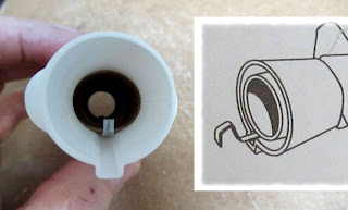
Dry fit the engine mount into the tube.

TIP: Slide in a turn the mount and shroud until you find the best fit against the tube.
Mark the best position with a pencil mark on the tube.

Now you can apply some glue inside the tube and around the exposed middle centering ring. Slide in and turn the mount until the pencil mark lines up with the shroud joint.


Form the wider shroud edge as before, rolling the burnisher over the tube and shroud joint.
This will make for less filling later on.


The raised shroud overlap can be sanded down a bit. Just lower the thickness a little, not too deep.

Tuesday, June 11, 2024

Semroc Wac Corporal Build, Part 9, Fitting The Tail Cone


The kit supplies one tail cone shroud printed on cardstock. I rarely get a good fit onto both tube diameters with one shroud.
I scan and copy at least three of them onto 110 lb. cardstock. Assemble all three - one of them should have the best fit.

Do plenty of dry test fittings for a smoother final look.
One shroud on the left is a poor dry fit, both ends are a bit wide.

On the right, one of the other shrouds and a better fit. Both the middle centering rings have been dry pressed into the wide end. The second ring is outside the shroud top and gives you an open edge for gluing and a slip fit of the ST-11 main tube. 


The lower ring is glued in place, even with the end of the motor mount tube.

I use the flat face of my sanding block to press the ring even.
TIP: There was still a very slight gap in the small end of the shroud. I wanted to increase the outside diameter of the low ring.

I applied a thin line of wood glue. Smooth and even it out using a fingertip on both sides of the glue ring.

After it dries, run a finger around the ring and you'll feel high and low areas. Some 400 grit will take down the high spots.

Friday, December 23, 2022

Estes Maxi-Brute Honest John (Kit #1269), Part 7, Nose Cone Cut & Trim


The lower end of the nose cone and the tail cone are molded in one piece.

Cut them in two around the deep indent line with a razor saw.


You are left with a rough ridge on both parts.

I sanded down the lip using 220 grit on a sanding block. Follow with 400 grit to smooth it out.

The low section of the nose cone won't fit into the upper section without trimming the inside molding lip down. 

The instructions recommend sandpaper, but I chose to do some careful shaving with a new #11 blade.


Almost all the molding lip is trimmed and sanded.

Slide on the upper nose cone section and check the outside seam for any raised areas. A raised spot might require some more trimming of the inside lip.

Monday, November 21, 2022

Estes Odyssey #7235 Build, Part 28, A Fix & Tail Cone Gluing

I rolled some masking tape around the inside of the tube before spraying the overall gloss white. I try to remove some of the stickiness by pressing and lifting the tape strips on my pants leg so it won't peel the inside layer of the tube.
Well,
Occasionally the less sticky tape will lift the inside layer.

I peeled out some of the inside layer from a scrap of BT-55.


This was glued into the tube and pressed in place. The tube is much stronger now.

The angles of the two tube wraps weren't the same, but the nose cone will fit will better.

The engine mount is slid in place, centering the hook on the bottom of the model.
Position the depth of the mount using the tail cone.

Do some tests fits before laying glue in the tube. In the end, the engine hook and tail cone slot have to line to line up and be centered under the model.

Sunday, October 30, 2022

Estes Odyssey #7235 Build, Part 7, Tail Cone Hook Relief

Take this step slow!
A notch has to be cut into the tail cone to allow movement of the engine hook.
Mark with a sharp pencil, 1/8" wide by 1/2" long.
Those half round vertical ribs are wider at the bottom. Keep that in mind when cutting out the notch.

Score the pencil line with a sharp knife.
I carved the notch out making small chip cuts from side to side. 
The top of the notch was squared up using a diamond file.

The sides were widened with the flat file so the 1/8" width would be consistent from top to bottom.
Check the width by sliding the engine hook in making sure it doesn't bind against the sides of the notch.

Wednesday, March 23, 2022

Estes Space Ship One, Kit # 2191, Build Part 3, Engine Mount Fitting

GOTCHA: Notice the engine mount tube was white and in this post is now brown. I ruined the kit supplied brown tube after gluing the centering rings in the "compromised" position before rounding out the tail cone hole so the ends could be even.
The rings were removed from the white tube. A new brown BT-20 tube was cut.
   
I had to round out the oblong hole using a half round diamond file.
When the hole was wide enough, some 220 grit sandpaper was wrapped around a used engine casing until a scrap BT-20 finally fit.

This took too much time to fix. I wonder how many of these kits were tossed in frustration or incorrectly assembled with the engine mount in the wrong position. 
This might be why so many were unstable before the extra 1/2 oz. of clay weight was added? (Remember, four pats of clay nose weight were included in the revised kits.)

For a better fit of the rings in the sloped tail cone, the edges were slightly angled using a sanding block. Notice I'm sanding both rings at the same time for consistent angles.

TIP: On the right - don't remove the turned over outside edges. This will leave you with a wider gluing edge.


TIP: When gluing in an engine mount you can slide in an expended engine for more support in the thin wall BT-20 tube.

Here's a correct fit of the engine mount, all the way through with the BT-20 engine tube and tail cone ends even. Whew!

Tuesday, March 22, 2022

Estes Space Ship One, Kit # 2191, Build Part 2, Engine Mount Fit?


There's no reason to place a line of glue inside the tube, then slide the engine block in from the bottom - 


Slide it in from the top and down onto the marked yellow tube held in position. Apply a ring of glue from the top.

The fins were laser cut but the centering rings were die-cut.
There's a few hold down tics that should be smoothed out.


The ring fit was too tight on the BT-20 engine mount tube. I wrapped some 400 grit around a used engine casing to widen the diameter.
I did some dry fits in the tail cone - Uh, oh!

GOTCHA: The pencil marks show where the instructions said the rings should go. I couldn't fit the engine mount in the tail cone unless I moved both rings about 5/8" to the rear. 
Don't glue the rings on yet - 
On the left is the mount fit in the tail cone. The mount slides in from the top. It stopped and wouldn't pass through the nozzle hole! 
Check the instructions. The drawing shows the rear of the engine mount tube even with the rear of the tail nozzle.

Look closely at the hole in the left side picture. It is actually more oblong than round. 
This will take some work . . .

Wednesday, March 31, 2021

TLP Hawk Build, Part 5, Tail Cone Fitting


The supplied centering fit was way too loose inside the main airframe  tube.
Some thin strips of cardstock were cut and glued around the ring to widen the outside diameter.


Here's the dry fit of the tail cone assembly ready to be slid into the larger BT-80 tube.
It's an interesting sub assembly - 
The 24mm engine mount will slide into the interior BT-70 tube. 


I used a brush to add a glue fillet at the ring / shroud joint.
I didn't want too much and run the chance of the glue shrinking and puckering the shroud edge.


A sparse ring of glue was set onto the bottom of the BT-70 interior tube. Don't use a lot of glue, when it dries it might pucker the cardstock.

The tail cone assembly was slid up from the bottom into the line of glue.
A fillet was added to the top ring joint.

Tuesday, March 30, 2021

TLP Hawk Build, Part 4, Tail Cone


This "kit" didn't include actual printed shrouds, but gave directions on how to make them in the instructions.
You could draw a big wedge piece but I didn't have any cardstock that large.

At first I thought the interior tube was a BT-70, but turned out to be a Centuri style ST-20.
I went to - 
https://www.payloadbay.com/page-Tools.html
and input the dimensions.
Note: Tube 1 is an ST-20, Tube 2 is a BT-80
The length should be 2.9". That was corrected before printing the shroud.


Here's the tail cone I printed on 110 lb. cardstock. 


This was cut out.
A glue tab was made and stuck to the shroud using a glue stick.

Thursday, November 12, 2020

Estes Asteroid Hunter #3224, Build, Part 13, Nose Cone, Tail Cone & Nose Weight


The nose cone and tail nozzle are molded as one piece.

I always double check before sawing them apart. Sometimes the molded rings could be mistaken for the line to saw through.


The hole in the back of the nose cone will have to be enlarged to get all the clay nose weight in.

Using a X-Acto blade and small files, I tried to round it out without weakening the shock cord/parachute tie loop.
TIP: Instead of rolling the clay into a "snake", try cutting the nose weight into small pieces and roll them into balls.
When the balls are dropped in one at a time into the hollow nose cone, they will likely settle more evenly at the bottom. Drop in four clay balls and tamp down with the end of a dowel. Drop in four more clay balls.
This is a whole lot easier than chasing a clay snake around the inside of the nose cone with a stick.

You've got to find a small diameter dowel to get all the clay into the strange shaped nose cone.

Holding the nose cone up to a bright light to see the clay inside. Try to get it as level as you can when tamping the 3/4 oz. of clay weight in place.