Showing posts with label Gotcha. Show all posts

Tuesday, July 1, 2025

Aerotech Mega Initiator #89541, Part 18, Setting The Name Sticker


From the last Mega Initiator post - 

With the O and R "cut" directly over the tube joint, sight down the body to make sure the orange line and type are straight. Tape down the sticker.  

Use your aluminum angle to check the orange stripe is straight.
The placement illustration says to overlap by 1/8", but I wanted to end up with a clean cut between the O and the R.
A 1/4" overlap puts the cut between the letters.

Double check the 1/4" overlay of the orange stripe joint before peeling off the backing.
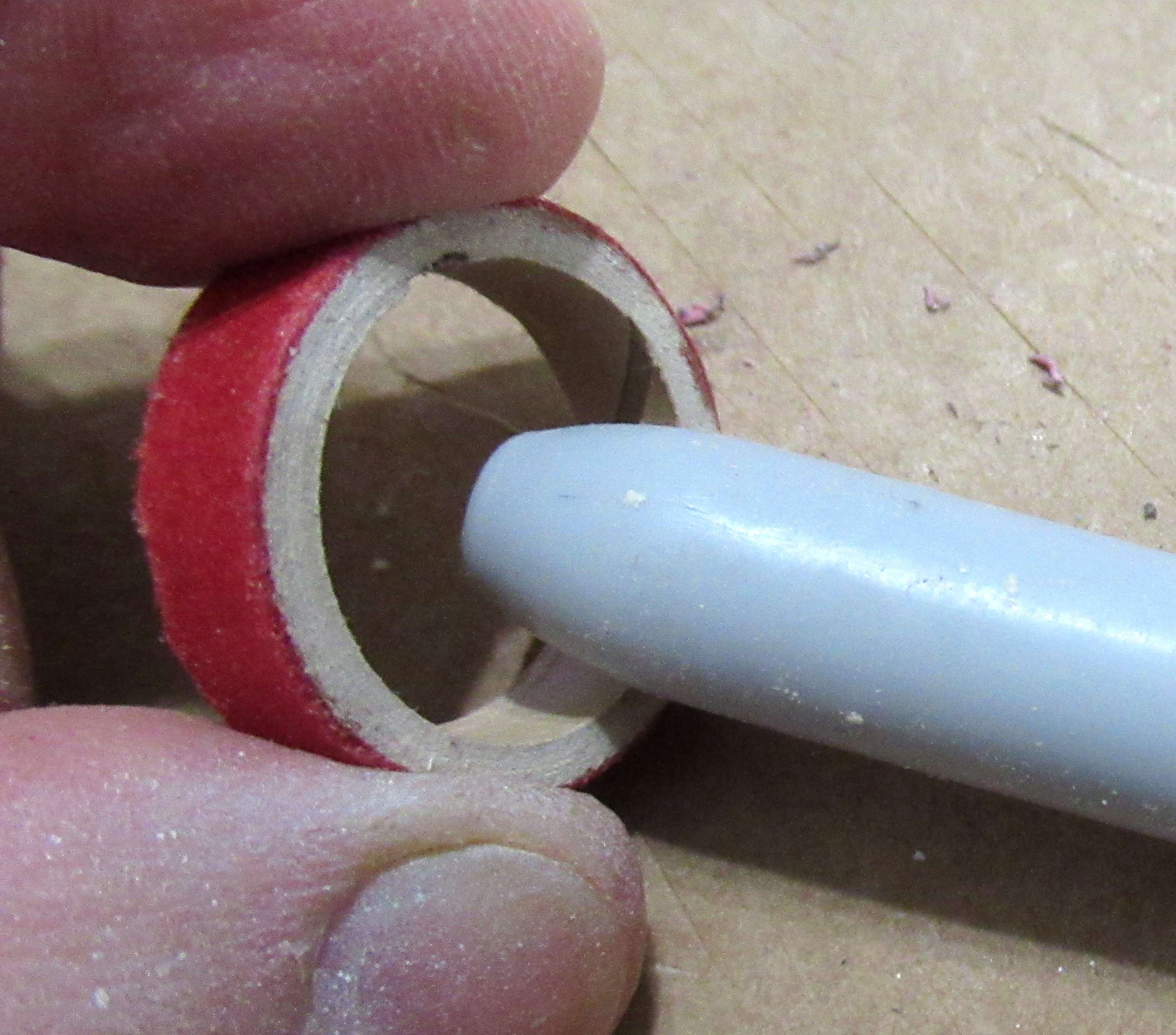
I peeled the backing on the orange strip and lightly held the  vinyl. The backing was cut off up to the R. 
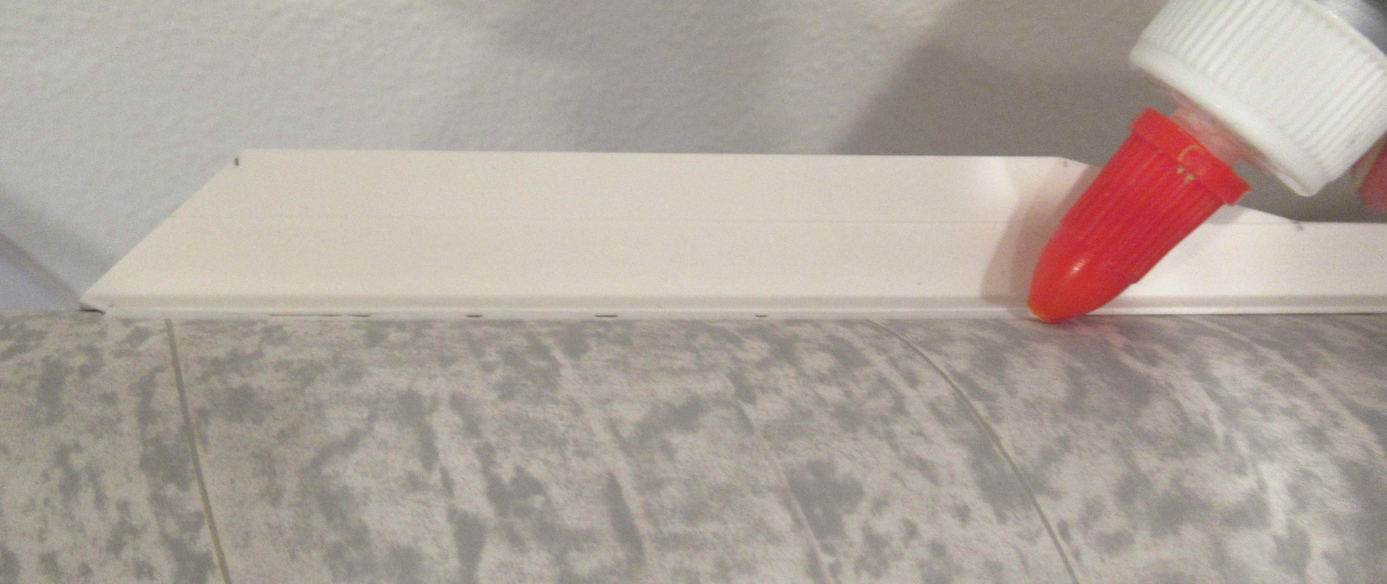
The orange stripe was set over the upper stripe matching the edges.
With the ends matched up, the backing is pulled under the name. Carefully set down the name checking the straightness as you go.
Add the "C" tail sticker at the low end of the orange stripe.

GOTCHA: The illustration drawing shows the "I" even with the top of the fins. The provided sticker lengths end up with the name higher up on the model.

Friday, January 17, 2025

Estes Black Star Voyager Build, Part 17, Marking The Tubes


From the instructions - 
You are directed to wrap the fin marking guide around the lower tube. This wrap fit very well.

GOTCHA: Not mentioned in the instructions - 
I'd recommend centering the engine hook between two of the "S" lines. You don't want the engine area vanes to hit the engine hook.
To go one step further, center the engine hook between two of the "SF" fin lines.


As in most instructions - 
You are told to extend the fin lines using a pencil and door frame.


TIP: I'd highly recommend buying and using an aluminum angle to extend the pencil marks, especially on larger models like this one.

Sunday, January 12, 2025

Estes Black Star Voyager Build, Part 12, The Lower Fins, Steps E


GOTCHA:
 
In the instructions, the before illustration is very thin compared to the after drawing on the right.
There is a slight taper sanded into the outside edges to better fit the "Q" side pieces coming up.


After sanding in the angle,
Here's the "Y" piece, lightly glued into the slot in the "X" piece.
Glue lightly, you may want to have it held like a glue "hinge" so it can be moved slightly for a better fit of the "Q" side pieces.


On a dry fit, no glue yet -
You can see the gaps in the "Q" side pieces.


The inside centers are sanded to a knife edge.
Mirror the other side.

On the right is the other side. You'll have to do some dry fits to figure out which angles are sanded into which sides. The instruction drawings are confusing.
 

Thursday, November 14, 2024

Enerjet by Aerotech Strong Arm Build, Part 14, Launch Lug Fit & Fillets

While the fit of the vane sides were pretty good, the edges could still use a fillet.
I used Titebond Quick and Thick with a smaller Elmer's glue bottle nozzle. 

TIP: On a long fillet like this, it's easier to glue and smooth about half of the length, then do the upper half. Too much excess glue can pool under your finger when smoothing out a long fillet. 


GOTCHA: The coupler end inside the upper slot prevents the front of the launch lug from fully seating.

I filed down the front half of the positioning tab to fit over the coupler.


Beacon Fabri-Tac was used to glue the launch lugs in position.

A piece of masking tape held it down while the glue sets up.


I'll be on vacation for the next five days, there may not be posts while I'm away.


Monday, October 21, 2024

Estes Star Stryker Build, #3206, Part 10, Decals - GOTCHA!

Vacationing in California - Drove past the elementary school where I launched rockets in the 1960s through 1970s. Sign of the times - gated and locked.

You get the impression the decals will be placed on both sides of three fins. The box cover picture shows two fins are solid red. 

GOTCHA: While it seems you have mirrored decals, these six decals will only fit on one side of the five fins.


So I'll set the fin decals on the right side of all five fins.
You'll end up with one extra.

This has happened in kits before. The decal print sure looks like the decals will be placed on both sides.


Do the wrap decal before setting on the name decal. You can better center the name decal in the open space after the wrap is in place.
The gray stripe was cut from the top of the decal and set it back from the top of the body tube and  expose a band of red paint on the tube.
TIP: I don't like to set wrap decals all the way to the end lip of the tube. That can cause the upper overhang decal edge to break and peel.

The name decal was set on the opposite side of the launch lug, centered above the root edge of a fin.

Saturday, October 12, 2024

Estes Star Stryker Build, #3206, Part 4, Joining Tubes & Fin Marking - Gotcha!


I sand the ends of the clear retainer ring with 400 grit to clean up the edges.
Here's the yellow coupler / engine block.
A line of glue is set inside the tube and the block is slid in until it rests against the top ben of the hook. 

Before gluing the long upper tube over the coupler - 
Slide the tube over the coupler (dry). Turn the tube until you get the best match of the two tube ends. Mark the position with pencil. 
Set a line of glue in the upper tube - slide over the coupler and turn so the pencil marks line up.

GOTCHA: The tube marking guide is printed a little wide to fit over the engine hook and retainer ring.
I marked the tube then rotated the guide to check the fin spacing against the next set of marks. It was off no matter how many times I turned the paper guide.

I went to payloadbay.com and printed off a new five fin marking guide. On the right you can see the difference between the two guides. The payloadbay.com guide is on the left.


The payloadbay.com marking guide was printed to fit a BT-20 tube.
I wrapped it above the engine hook and marked for the fins. Extend the marks down the tube.

Saturday, September 28, 2024

Enerjet by Aerotech, Arreauxbee-Hi, Part 7, Engine Mount - Gotcha!


The fin-lok rings were very tight - 
too tight to slide onto the motor mount tube.

The inside walls were shaved wider using a #11 blade.
Shave a bit, test the fit.

You want a tight fit on the engine mount tube.


The fit of the plywood centering ring was tight and needed to be slightly widened. 

I shaved a bit off the inside diameter for a tight slip fit.


The rings were slid into position at the recommended measurements and glued on using medium CA.

The third upper ring was glued over the face of the baffle plate.


The fin tabs wouldn't fit into the fin-lok rings with the rings at the recommended positions.

The instructions say the front edge of the rear ring should be 1 1/4" from the rear end of the tube.
GOTCHA: The front edge of the rear ring should be 1 1/16" from the rear end of the tube.


Look to the inset picture at the upper right.
I had to cut and extend the lower notch up about 3/16" for the fin to snap into place.

Sunday, February 25, 2024

New Way Nike Ajax Build, Part 9, Tunnels Shaping

I thought the balsa tunnels would be too weak when trying to sand the trapezoidal shape into the sides. (See last picture below.)
I cut them out of 1/16" thick basswood using a kit supplied balsa piece for a template.
Here's four of the upper body pieces below the original kit piece.
GOTCHA: Well, got me anyway! I cut the lower, longer tunnels were fine cut from basswood. They fit a straight  tube surface well. 
On the upper, shorter pieces, the kit supplied balsa is more flexible. The balsa strip is easily pressed into the adapter dip and over the nose cone shoulder curves. I ended up having to cut notches in the upper basswood strips and "cracking" the wood slightly to fit the angle changes. More on this later.
If you want an easier build, stay with the balsa strips supplied with the kit. But, the balsa grain is more difficult to fill.


The strips are sanded to a trapezoid shape, shown below.

I marked the tunnel sides with a soft pencil. This gives me a better contrast, I can see what is sanded off.

Use a sanding block to keep the side corners sharp.


Looking from the back end, here's what you should end up with - 
The basswood is stronger and will hold up to more aggressive sanding.

Monday, October 2, 2023

Estes Black Brant XII, Kit # 9723 Build, Part 18, Scattered Build Pics


This blog build probably hasn't followed the instructions order. Many of the parts were painted before gluing the model together.
Here's two of the first stage fins.

GOTCHA: The Finishing Picture on Page 10 of the instructions says to paint all four of the 1st stage fins yellow. Actually, there are three yellow fins and one red fin.
The second stage fins are three red and one yellow.
The single first stage red fin lines up with the single yellow fin on the second stage.


The area under the third stage fins is flattened for a better fit of the plastic fins.

The instructions show a sanding block being used. I used a flat diamond file for more control. The block is too big, with a file I could see what I was sanding.


Here's all the black parts ready for paint.


On the largest adapter shown at the right - 
The orange was sprayed first. A straight line mask went around the bottom of the orange. Another white under coat was sprayed before the silver was added.
Silver was sprayed and allowed to dry. 

Sometimes it's hard to get a clean mask line in a recessed area.
TIP: I used a ultra fine point Sharpie for an easier, sharper mask. The black pen ink filled the recess area. Masking followed, then spray black paint.

Monday, April 10, 2023

Estes Klingon Battle Cruiser, #1274, Step 20, Wing Gluing? Gotcha!


Here's where I screwed up!

The instructions show a slight down dihedral here at the right center illustration. 


I thought the center tips (here pictured towards the front) should be touching. There is no reference to this in the instructions.

The low tips of the front and rear hanger bulkheads touch the wing face in the rear.

With the front tips touching at the top centerline and the root edges down their pencil lines, there is very little dihedral angle on the wing sides.
The only reference is on the last page showing the decal placement.
My model doesn't have this much down angle on the wing sides.

GOTCHA: To get more of a down dihedral -
You would have to have a gap between the center wing tips over the body tube. 
The long root edges of the fins might have to be glued a little below the pencil lines on the body tube.

Wednesday, April 5, 2023

Estes Klingon Battle Cruiser, #1274, Step 15, Warp Drives & Wings

The sides of the Warp Drive pieces don't want to stay together. When you glue down one side, the other side opens up.
Earlier posts had the interior support tubes sanded down so the edges could touch.

More liquid plastic cement with finger pressure on both sides while the glue set up.


The large wing assembly is are confusing. Darn Klingons!


Here's how they actually look. The root edges are facing each other.


The front hull piece joint needed some CWF fill, the filler/primer and sanding.

On the right the front hull piece fits well over the BT-50 main tube. Do plenty of dry fits before gluing the wing in place.

GOTCHA: Those tips above the round center area do not have to touch! If they touch you might not get the angled "down" dihedral. Most of the gap between the tips will be covered by the Access Boom Detail vacu-form piece. 
Check the decal drawings in the instructions. The outside edge of the wing should be below the centerline joint (pencil line) at the body tube. 

Monday, March 27, 2023

Estes EAC VIPER #0820, BT-55 Upscale, Part 10, Fin & Launch Lug Gluing


The rear fins are glued .35" from the end of the tube. Two fins are centered around the engine hook.
.35" was pencil marked in one location. 
For consistency, I wrapped some cardstock around the tube at the pencil mark. The other marks were made against the cardstock edge.


I do two-step glue fillets.

On the left is the first Titebond Original wood glue fillet.
The dried fillet shown is a bit rough.

After that dries, a second fillet is made using Titebond Quick and Thick glue.

GOTCHA: The upper short launch lug is glued .35" from the top lip of the body tube.

Look close at the picture. 
There's a problem with the purple wrap band decal. It runs into the upper lug.
If I were to build this model again, I'd set the upper launch lug at least 3/4" below the top of the tube so I could do a complete wrap of the purple band.

GOTCHA: Look at the ESTES AEROSPACE CLUB decal running down the body. There were two name stickers on the sheet, I mistakeably drew up the longer sticker. While I used the longer decal in this build, the PDF was corrected for the shorter length decal. 


Here I'm rounding over the edges of the launch lug glue fillets.
This was glued in place before I realized the lug would be in the way of the wrap decal.

Wednesday, March 1, 2023

Quest Icarus Build #Q2006, Part 4, More Prep & Mistakes!

The yellow motor tube is pre-notched for the engine hook.

Well - The knife punch is too high for the upper bend of the engine hook. It has to be 1/4" down to allow for the engine block to fit flush with the top of the tube.
I made a new slit at the correct position. The wrong knife punch will be fine with the glued in engine block underneath it.


The red centering rings had raised cut off burrs on the inside.

Press and smooth these down with a burnisher for an easier slide over the motor mount tube.

GOTCHA: There is a small mistake in the instructions.

The drawing shows the fins marking guide wrap still on the body tube with the fins glued on top! "Position finds on guide lines?"

Remove the marking guide, then glue on the fins.

I made a mistake!
The instructions don't mention not using the launch lug standoff. I used it. 

Not a big deal, but the launch lug can be glued directly onto the body tube without the standoff.

On the left is a flight model with the balsa fins.
On the right, the show model with filled body tube seams and stronger basswood fins.

Thursday, December 1, 2022

Estes Blue Origin New Shepard Build, Part 3, The Tunnels -Gotcha!


There are some small balsa pieces in the kit.
Play it safe and store them in a zip top plastic bag until you need them.


I used a new #11 blade to cut through the hold down ticks and remove the tunnels and ends.


I'd recommend using a sanding block to lightly remove the ticks for a better fit of the ends onto the long tunnels.

TIP: I decided to glue the bottom ends onto the tunnels now to get a flat alignment. It would be easier to fill the joint and wood grain before gluing to the model. The instructions show the ends glued on later.
Here's a dry fit - The tail cone isn't glued in yet.
The low end fit is good.

On the top side - 
GOTCHA! The tunnels were short by about 1/16"! The tunnel should be long enough to reach the end of the tube. A fix is coming up in the next post.

These two kits were probably pre-production. These things are usually taken care of before kits are sold.