Showing posts with label Boost Glider. Show all posts

Tuesday, May 14, 2024

Estes Condor #0807 Build, Part 17, Fitting The Wing


On the left - 
The V tip of the two wing pieces leave a small gap at the fuselage notch.
Looking at the back, the wing overhangs the rear of the fuselage.


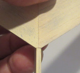
By slightly sanding the "V" tip, 
it closes the small gap at the front and moves the wing forward. The back of the wing is now even with the tail end of the fuselage.


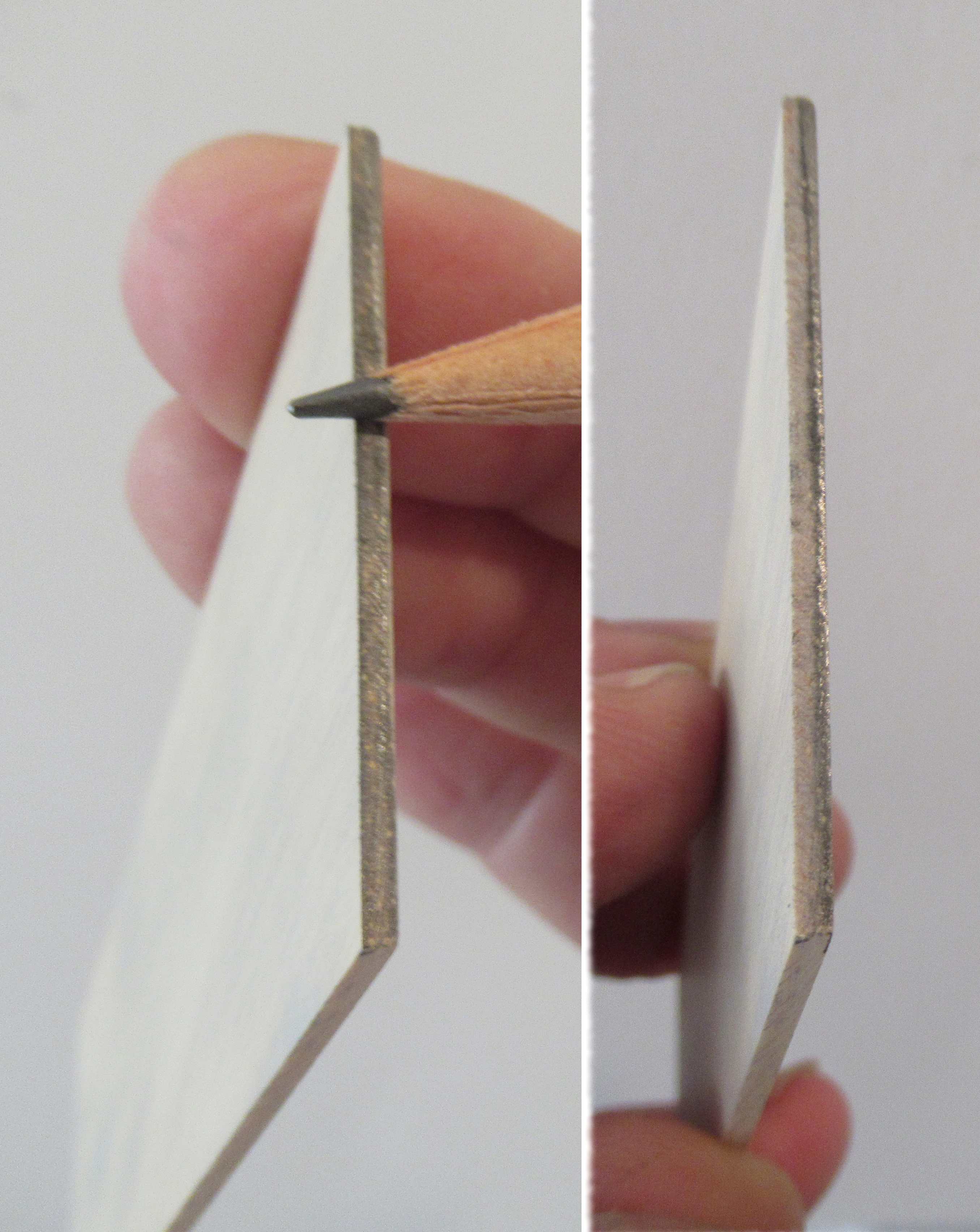
I drew a pencil line down the center of the canard for gluing alignment.


The dowel is glued into the notch at the front end of the fuselage.


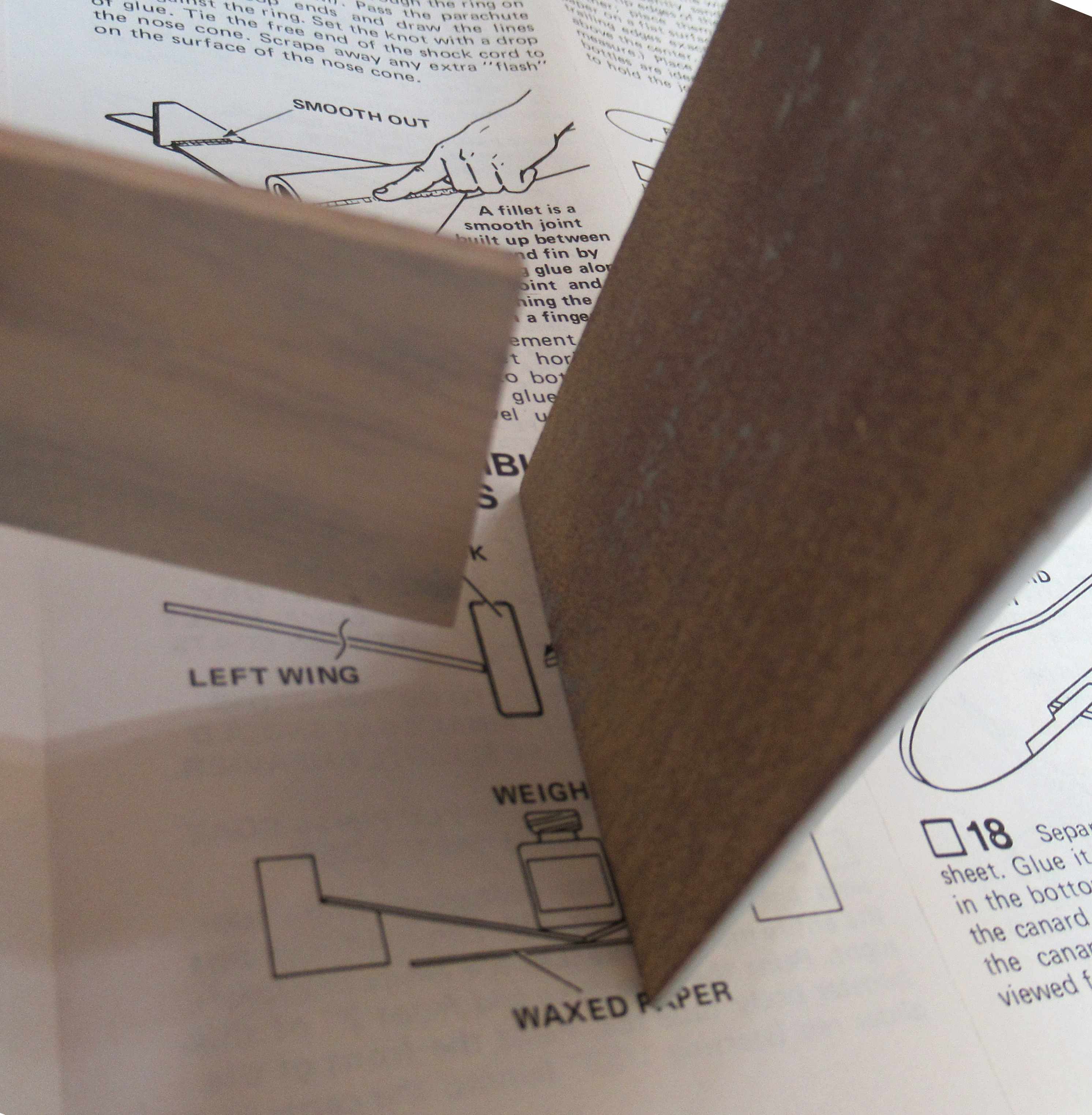
Check the instruction drawing below - 

On the left is how the tip plates will glue onto the outside edge of the wing.
On the right - I sanded the outside wing edge to get the tip plate to the correct angle.
Here's what I was going for - 
This illustration is from the instructions in the countdown checklist. It probably should have been brought up in Step 20.

Sunday, May 12, 2024

Estes Condor #0807 Build, Part 15, Gluing Up The Glider


The stabilizer is glued onto the fuselage.

Do your best to center the thinner piece on the thicker stock fuselage.


The wing panel root edges should be sanded to an angle for a stronger glue bond.

I mark the edge with a soft pencil so I can tell what has been sanded.
On the right side, I'm about half done sanding the angle, you can still see some pencil marking left.
Sand until the pencil mark is gone. 


I used the instruction illustration to get an idea of the wing edge and sanding block angle.

The wing half is on the left, the sanding block is on the right side.
The dihedral guides are on the back of the face card. I didn't want to cut up the face card.

I extended pencil lines and transferred those onto some thick cardstock. The cardboard was cut out for the next steps.

Tuesday, August 9, 2022

Estes Super Orbital Transport Build, Kit #7314, Part 14, Gluing On The Glider Wing


Mentioned earlier - the glider marking guide was too large. This was a pre-production kit, I'm sure corrections were made.

I made another one out of some copy paper. It's simple, the tube is marked twice on opposite sides of the tube.


I had already filled and primed the balsa pieces.

Some 320 grit was wrapped around a Q-tip and the center gluing area had the primer sanded down to the CWF - no lower. Just remove the gray primer.
This is all the glue I used to adhere the wing to the tube. I didn't want glue to be pushed out and seen on the finished model. 
TIP: Don't attempt to apply fillets into the tight wing/tube joint. You'll end up with bubbles and too many glue applications trying to get rid of them.


Earlier I had extended the pencil line inside the tube for alignment with the wing joint.


The tip of the wing seam aligns with the pencil line running down the tube.

Thursday, August 4, 2022

Estes Super Orbital Transport Build, Kit #7314, Part 9, Glider Wing Dihedral Angle


GOTCHA: This was a pre-production kit, any mistakes in the instructions are taken care of before being available for sale.

The Glider Marking Guide was too wide.

It's a simple tube to mark, two lines on opposite sides of the BT-50 tube.
I'd recommend using 220 grit on a sanding block to get the correct sanded angle on both sides of the inside wing edge.

Mark with the side of a pencil, darkening up the flat edge. As you sand, you'll see the contrast between the penciled flat edge and the sanded lighter bare balsa. 
Sand and check, sand and check. You should be using a sanding block for this type of angled edge.


The two wing sides are glued together.
The picture shows a good fit between the two pieces. 
The cardstock "P" piece is underneath the right wing half.

Monday, March 23, 2020

Semroc MMX Orbital Transport, KMX-01, Build Part 9, Orbiter Glider Construction


GOTCHA: Something wasn't right. I had built three other full size Orbital Transports before.
Check the instruction photo showing the glider body tube. The front extends probably 3/8" beyond the front center tip of the wing. The kit supplied tube was too short!


Luckily I had some MicroMaxx sized tubing in the spare parts drawers. 


Good thing I didn't add those wing glue fillets!
I used a single edge razor blade to remove the wing and rudder. The new longer tube was glued in place.
The orbiter nozzle shroud is tiny!
You can pre-form it using a sharpened dowel end.

The glue tab was held shut with tweezers while the glue set up.
TIP: Use very little glue to adhere card stock shrouds and nozzles like this.


The nozzle is glued to a small disk and coupler to be slid into the rear of the glider body tube.

Sunday, March 22, 2020

Semroc MMX Orbital Transport, KMX-01, Build Part 8, Orbiter Glider Construction


The dihedral of the glider wing is done by setting the joint over the glider body tube. When the outside tips of the wing sides touch your work bench, the angle is correct.

I also filled the joint at the wing center.


The instructions suggest glue fillets along the top joint of the wings.
I wouldn't recommend this - it isn't needed. Getting a bubble free fillet is difficult and adds a lot of weight.


One side of the template jig is used to set the elevon angle.


The notched hook is glued even with the front of the wing.
GOTCHA: Notice anything wrong here? More in the next post.

Monday, February 24, 2020

SR-71 or SR-72?


On the NAR Facebook page, Frank Burke posted a picture of his latest R/C Boost Glider:

"YF-12 interceptor version of the A-12/SR-71 family. Hardly ever modeled. This was an interceptor version that wound up being used for testing the aim 47 missile and doing tests for NASA. The chines were shorter on this design because of the large rounded nose cone that held the radar system. The R/C Rocket glider uses 9mm depron, bt80 tubing and is designed for 32mm glider G-12 reloads. Currently 16 oz airframe weight. with electronics, paint, nose weight and motor it'll be about 26 and 1/2 ready to fly so it should be a pretty good performer."


I thought this profile looked familiar. I put together the (much smaller) Apogee SR-72 Darkbird a while back. 
To see the build: CLICK HERE

At the time, I asked Tim at Apogee where he came up with the name. He said: "We wanted to show the next generation of the SR-71, we call ours the SR-72."

Looks like the Apogee kit was based on the same YF-12 Interceptor that Frank built. I never even knew it existed.

Sunday, September 29, 2019

Estes Solo #7288 Build, Part 5, Cutting & Forming The Glider


I don't know what I was expecting, maybe a large tube like in the Flying Stovepipe plans. The body of the glider is rolled card stock.
(Don't stare at the printed circles too long - you'll be hypnotized!)

There is a thin yellow line to cut on with scissors.


I shaped the ring glider as always by using a dowel.
Set the card stock in the heel of your left hand. Press and slide the (clean) dowel over the card stock for a smooth round shape.

Curve the "arms" at the top until they touch.


On the left side a piece of Scotch tape is pressed.
Center and join to the right side.

Apply tape to both sides


The round glider body is slid into a slot running around the connecting ring.
The joint on the card stock body lines up with a molded line between the two molded lugs.

Wednesday, August 28, 2019

Estes Gryphon #7280 Build, Part 7, Glider Assembly


A line of glue was set at the center of the canard. It was slid in place.

I looked straight on the front of the glider, the canard was canted at a slight angle.


TIP: Before the glue could set up, I slid a wedge of balsa into the joint to raise one side and straighten it out. The wedge was easily removed after the glue dried.


The finished glider ready for a coat of gloss light gray paint.


Moving back to the boost pod - 

The shoulder insert on the BT-5 sized nose cone had a raised ridge making it a rough slide into the body tube.
The ridge was sanded down with 220 grit on a block.

Thursday, August 22, 2019

Estes Gryphon #7280 Build, Part 1, Parts

I want to call this one "Gry-fon" but it is pronounced "Griffin".
From Wikipedia: The griffin, griffon, or gryphon is a legendary creature with the body, tail, and back legs of a lion; the head and wings of an eagle; and sometimes an eagle's talons as its front feet."


Here's the kit parts in the bag -

Some have posted they see a resemblance to the OOP Edmonds Aerospace kits. The new Gryphon is a rear wing, canard design but that's where the similarities end.

Also included in the kit is the Launch Controller Wire Standoff. This standoff helps hold the controller wires and clips away from the lower wings of the glider. A smart addition.
On the right are the black and white decals.

Sunday, June 2, 2019

Felt Tip Pens on Boost Glider TIP

A photo from Ed Mitton's Blast From the Past Blog:


"Yes, the FlatCat was colored with permanent markers. Before applying the markers, the glider was shot with a coat of Duplicolor white sandable primer, then sanded smooth with 400 grit paper. This 'seal' coat keeps the marker colors from absorbing into the grain and running. The white undercoat also makes the marker colors pop.
Since this model is being flown only for sport, I'm not at all concerned about any additional weight from the primer.
The glider that this one is replacing was finished in the exact same manner, and rode away on a thermal on its first flight (B4-2 motor). I had it in sight for well over 5 minutes before I lost it."


That's a great tip - using the white sandable primer before using the felt tips pens!
I've used felt tip pens on raw balsa before and the ink can run outside the desired 

color separation lines.

Ed's Model Rocket Blog can be found at: https://castlerocketeer.blogspot.com/

Wednesday, January 9, 2019

Estes Orbital Transport, Kit #K-42, Part 19, Orbital Glider Decals

The gloss white finish coat on the glider was dry before the larger booster assembly.


The Semroc Orbital Transport decals (and maybe the original Estes kit decals) are tightly arranged on the sheet. Look how close the glider decals sit next to the long red booster stripe decals.

You might have to use a sharp knife before trying scissors.


I set the tail section decals on first - no problems so far.


The "Semroc Astronautics Lines" decals were cut off for my home printed "Astron Aeronautics Lines" decals.

Sight down the front to be sure the decal base is in a straight line. That tapered tip can easily slide up and down. This red decal actually sits a little below the center line.
Here's the replacement decal. It ended up the same size as the original. On this side, the "A" in Astron lined up with the start of the rear, red taper.

The front of the tube isn't bent down, that's just some distortion in the image.

Thursday, June 28, 2018

J & H Aerospace Boost and Rocket Gliders


On TRF, Rktman posted a Swing-Wing boost glider build (CLICK HERE) from a vendor I didn't know about.
J & H Aerospace produces swing-wing boost gliders, standard boost gliders and Micro R/C boost gliders. To visit the website: CLICK HERE

"J&H Aerospace was founded by Joshua and Hope Finn in March 2015. We specialize in model airplane designs and components of unique design that are not available from any other supplier. Our products are proudly made in the USA from top quality materials.
In addition to the products offered here, we take custom orders including new product design. If you see something here that interests you but doesn’t quite fit your needs, please contact us!"

Wednesday, December 13, 2017

The Worst Kit?

I was asked recently what was the worst kit I ever built?
That's a hard call, I don't want to offend any vendor. Here's one from a company long out of business.

The Die Fledermaus was a boost glider from the Union Stadt Zepplin Works.
The picture on the right is from a review by Matt Gillard on Rocket Reviews: CLICK HERE

In my old rocket binders I found a 1977 letter from Robert Haley, the president of U.S.Z.W.
Robert was interested in me doing a review of his kit. My review would not have been favorable.


Matt Gillard had the same results I did. The build was difficult with vague instructions.
The written instructions were on one side of an 8 1/2" x 11" sheet. Enlarge the picture on the left.
The promo page called it a rocket plane. Rocket gliders (by NAR definition) don't eject the engine.


The full size assembly drawing was on the other side.
You have to warp balsa around the fuselage and form the nose from a block of balsa.

The A3-2t engine would eject and was supposed to glide at a 6 to 1 glide ratio.
Mine got 20 feet up and power pranged into the ground!