Showing posts with label Assembly. Show all posts

Saturday, March 30, 2024

Estes Skytracer Clone #1361 Build, Part 15, Gluing On The Thrusters

The instructions say to paint the thruster nose cones flat black.
I still have some Metallic Black and decided to go with that.

This is how I tape a nose cone down for spraying.
One wrap of tape, cut strips on the overhang and splay out.
Stick to some cardboard for spraying.


Here's that metallic black paint. I like it better than flat black.


Here's the view from the rear.
I found these hard to line up while the glue was setting up..


Both of the thrusters in place.
No color masking! 
The decals will make it more interesting.

Saturday, March 23, 2024

Estes Skytracer Clone #1361 Build, Part 8, Filler/Primer & Dowel Detail


After sanding smooth the CWF - 
The wing fins, standoffs, launch lug and standoffs were taped to scrap cardboard and sprayed with filler/primer.


After drying and before sanding - 
You can see some dulled areas of the balsa needed another shot of filler/primer.


The wing fins were glued onto the main airframe tube.

I thought the dowel went all the way from the engine tube to the outside edge of the fin rear. But - 

The dowel end is about 3/8" from the outside edge. I checked the instruction drawing this time.

Saturday, October 7, 2023

Estes Black Brant XII, Kit # 9723 Build, Part 23, Assembly


I wouldn't recommend applying epoxy to the fin tab then sliding it into the slot. That would squeeze epoxy out into the fillet area. It'd be a mess to clean up.

I applied epoxy into the fin slot using a toothpick, then slid the fin into it.


A rubber band was used to apply pressure on the fin pushing it into the fin slot for a tighter fit.

You do have to check the alignment before the epoxy sets up. The rubber band can pull the fin to one side.
Glue in the fins one at a time only after the epoxy has set up.


The launch lugs are centered between two fins.

Looking from the lower lug - 
The upper lug segment has the balsa standoff. 


The Kevlar cord is slipped through the back end before gluing on the second stage orange tube.

You can see the epoxy glue inside the body tube right before it was slid in place.

Saturday, April 8, 2023

Estes Klingon Battle Cruiser, #1274, Step 18, Engineering Hull Prep


The engineering hull top is a curved piece of cardstock.
Gluing flaps are folded underneath the exposed top. I burnished mine with a Sharpie pen barrel.


A close up shows the broken edges at the card stock fold.


A rub of medium CA glue was applied with a Q-tip. This hardens the fuzzy edge so you can sand it square with a sanding block.


The hold down tics are smoothed down with a sanding block.
I did some dry fits and found the cardstock front  wouldn't follow the curvature of the vacu-formed hanger deck piece.

A curve was pressed in the same way I curve a card stock shroud. 
Set the card stock over the soft heel of your hand. Press and roll the Sharpie barrel over the card stock. You should get a curved top. 


A dry fit - 
much better.

Thursday, April 6, 2023

Estes Klingon Battle Cruiser, #1274, Step 16, Hanger Deck Assembly & Wing Gluing


Earlier in the build, I glued the entire hanger deck assembly together thinking it would be easier to fill the joints before gluing onto the tube. The instructions have you assemble it in separate steps.

That may prevent some repeat fill steps, but I still have to fill the joint around the low end of body tube!


After CWF and sanding I still had to do a shot of filler/primer. 
The top of the hanger deck was masked off.
The catalog picture of the Klingon ship has a reverse or down dihedral of the wings. When gluing on the wings, mine ended up almost flat with a slight dihedral. Mentioned earlier, I thought those small tips at the top should touch. The instructions do not mention the down dihedral until you see the decal placement later on.

Here's the assembly turned over.
The wing angle is equal on both sides, there is some camera distortion.


Still turned over, 
you can see the root edge which will get a glue fillet.

Saturday, November 19, 2022

Estes Odyssey #7235 Build, Part 26, Silver Mask, Chrome Trim & Gun Gluing

I love a simple mask!

The vanes and area either side of the leading and trailing edges of the vanes is painted silver. 

Scotch Tape initial mask and masking tape outside those. Plastic bags covered the rest of the body.

I had already test fitted the chrome strip around the front of the gun tube.
Start and finish your wrap where the seam won't be seen, inside facing the fin leading edge.

The front of the gun was slid in place.
A Q-tip was used to apply a drop of glue. The Q-tip was then used to spread out an interior fillet and pick up any excess glue.

On the right is the finished wing tip gun.

The plastic nose cones were glued in using - 
Everybody say it out loud on the count of three - 
Beacon Fabri-Tac!

Thursday, November 10, 2022

Estes Odyssey #7235 Build, Part 17, Slightly Shortening the Inside Rear Engine - Fix


I double checked the instruction sheet measurements, I thought I may have got them wrong.
My centering ring gluing locations were correct. The inside tube will have to be shortened.

I cut a short length of BT-5 diameter coupler I found in the spare parts drawer. The edges were rounded for an easier slide into the BT-5 tube.

A wrap of tape was applied for a straight cut line.
The tube was cut near the center.


A small sliver was cut and and the engine assembly was slid in to check the length.

I cut three harrow slit segments until the vane tips were even with the front of the angled tube. 
The coupler was glued into the lower launch lug side at the halfway point. I didn't glue the front on yet. This will allow a turn adjustment to center the forward vane position when it is glued in later.


And, a dry fit.
At the rear, the lug ends are even and the forward vane tips are just inside the edge of the tube.

Friday, September 16, 2022

Estes Space Shuttle Columbia Build #1385, Part 5, Gluing Up The Wing

The wing is glued up from eight pieces of die-cut balsa.

Here's the back end showing the near fit.
Some block sanding was needed to get a tighter fit of the edges.
I look for areas that are touching and lightly sand that area. That should bring the glue edge gaps closer together.

 
What looks like a little hole in the upper picture is a small die-crush bit. that will be filled when the entire wing is painted with CWF.

The center pieces were the worst of the group.
The centerline was sanded again where the edges touched until I got the best fit.


This is a dry fit of the assembly - no glue yet.

The fit of the joints is much better.


I was more concerned with the inside joint fits.
The outside edges are easily cleaned up and rounded off after the glue on the entire wing assembly has dried.

Wednesday, August 10, 2022

Estes Super Orbital Transport Build, Kit #7314, Part 15, Gluing On The Engine Housings

Mentioned earlier - 
I sanded off the tabs (on the engine housings) and left the balsa notch slots in the wings. I thought it would be easier than filling the low tabs slots later.

This shows the top surface of the wing. Note the gluing areas for the vertical fins are sanded through the primer, down to the (glue soluble) CWF filler.
The inset picture shows the area near a fin root edge sanded down just through the primer for a stronger wood glue bond and fillet.


The engine housing assemblies were glued in place and the joints filleted.
The bottom of the wing assemblies had already got some early shots of Gloss White before gluing onto the body tube to be sure the fillets were smooth. Any glue fillet ridges were lightly sanded and paint shot again.
In the above picture the wing has been glued on. The support jigs are under the wing and the smaller forward stand under the body tube.

I continued the pencil lines around the inside end of the body tube. With the wing in place, the pencil line down the body tube would be covered. 
TIP: The wing and forward strake long fillets should be done in two passes. This prevents the glue bead from pooling up and getting too wide under you smoothing finger.

Lay a line of glue down from the center of the root edge and smooth to the rear. Lay down a second, forward line of glue down the remaining 1/2 of the root edge and smooth to the front.

Wednesday, August 3, 2022

Estes Super Orbital Transport Build, Kit #7314, Part 8, Wing Tips & Engine Housings


The wingtips are glued on, here shown upside down.

After the glue dries, CWF filler is brushed over the tab/notch seams.
I chose to sand off the tabs and leave the notches filled on the wings. While it's easier to align the engine housing sides using the cut slots, it takes much more work to fill the tabs that usually end up beneath the surface of the open slots. 
Oops! I did run into a problem  - of my own making. I probably sanded off too much!
Sanding down the tabs may have slightly lowered the height of the engine housings. The BT-20 jet tubes wouldn't comfortably fit under the housing assemblies.
I wrapped 400 grit around an engine casing and sanded a very shallow dip in the top surface.


In the picture above - those little dots help me keep track as I assembled three kits. The marked pieces all came off the same balsa sheet. 

The finished look is good. Those subtle dips under the top piece aren't noticeable.

Note the right and left rounded corners of the engine housing.

Wednesday, July 13, 2022

Estes Blackhawk #2053 Build, Part 12, Front Plates & Canopy

The top and bottom front plates are creased to fit and cover the open area at the tp of the rear assembly.

The embossed lines were folded over the edge of my straightedge.
The forward bend was creased sharp using a burnisher.
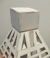
Here the model is upside down with the bottom plate facing up.

Here's how the front looks. Notice the "sandwich" of the lower plate bend, the thick central plate in the middle and the upper plate front bend.
 
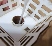
The canopy marking guide is set to the left and the inside line traced with pencil.
Flip it over and trace the other side.

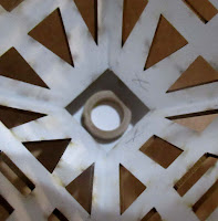
Do some canopy dry fits. The inset picture shows the canopy front where the cut out angle fits over the fold of the front plate.
You'll find the right and left side of the canopy has to open up to match the traced pencil lines.
Before gluing the canopy on, I reformed the canopy base wider than how it ended up after gluing together.

Rather than set glue on the very thin inside edges, I held the canopy on the pencil lines then applied short shallow glue fillets. 
When gluing thin cardstock like this, you don't initially need much glue.

Tuesday, July 12, 2022

Estes Blackhawk #2053 Build, Part 11, Gluing Top & Bottom Plates


There's the two internal vent tubes with the BT-50 main tubes glued to the outside.
So the ejection charge goes up - turns left - then turns up again to blow out the parachute. The tube on the right side doesn't have a parachutes.


Look close to see the glue line down the side top and bottom plates. See the picture below for positioning.

These really add to the strength of the whole unit.


On the left is the top plate. There is a long notch for the engine hook movement.

On the right is the bottom plate. There are cut out panels that will be covered with thinner cardstock pieces. This might have been done to reduce weight on the back end. Down the middle of the bottom plate is a pencil line for the launch lug positioning.

Saturday, June 11, 2022

New Way Boxie Birdie, Build Part 5, Assembly


Check the fit of the nose cap and trace around the edge with a pencil.

Apply a line of glue around the inside edge and press in place. 

Check to be sure it is level and even before the glue sets up.  

The engine mount tube gets a line of glue inside the end to slip around the engine block already in place.

Slide in and over the engine block.
Some glue will be pushed up inside the tube at the bottom of the engine block. 
TIP: It's a good idea to remove as much of the glue as you can. I used a long Q-tip to remove the excess glue.

It's probably not a concern with this rocket as the engine is ejected. But on other models, a hot engine could melt glue on the inside of the engine mount tube making it hard to remove.


The cap is in place - 

The square launch lug is glued into the rectangular hole and through the centering square inside. The top is even with the low edge of the cap assembly.

Friday, June 10, 2022

New Way Boxie Birdie, Build Part 4, Gluing Together The Body


The inside joints got a light white glue fillet. 
The glue was smoothed out and the excess removed with a Q-tip.


While the glue dried, 
the cage was held together with the cap slid in place - no glue.

You can see the engine block inside the top.

I set the rear centering square in place and leveled it as best I could.

The corners were marked with a pencil.
Small bits of glue were set at the pencil marks.
The plate was pressed into the glue dots and leveled.


Fillets were added to the plate/cage joints.
Use White Glue so it dries clear.