Showing posts with label Warped. Show all posts

Tuesday, March 12, 2013

Warped! Finished


This was one of the stranger builds.
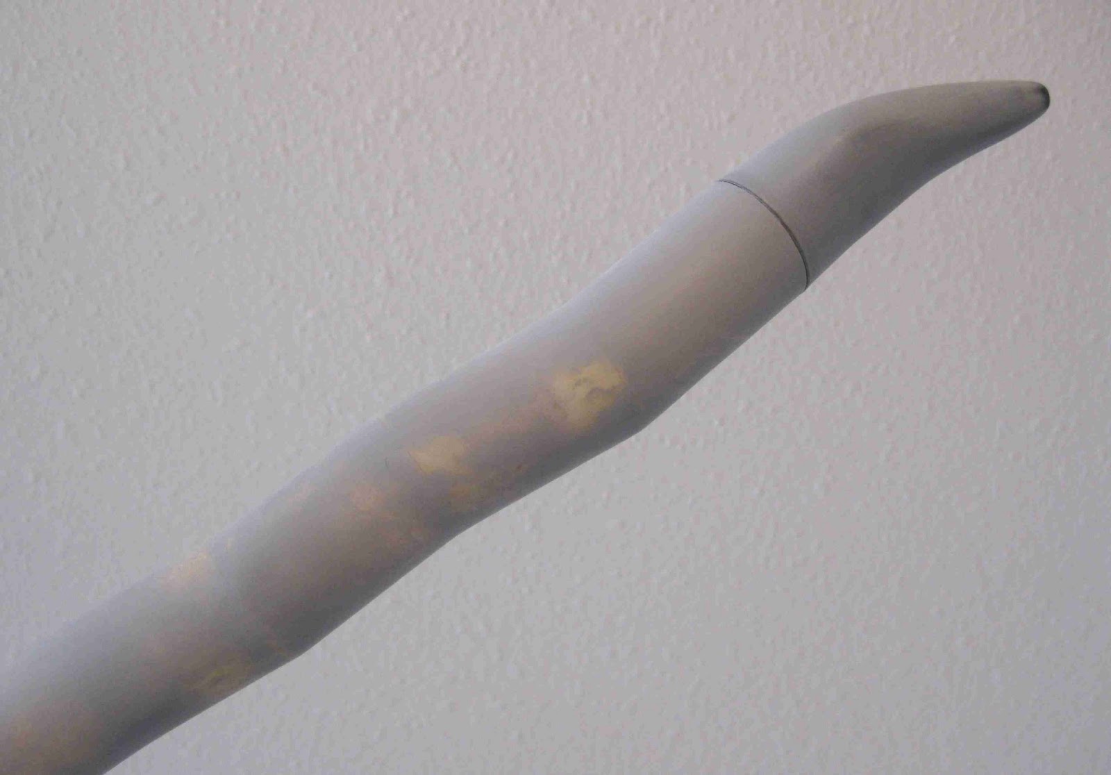
The angle of the upper full picture doesn't really show off the bends in the body.
I like a challenge, the warped nose dictated which way I should go with it.
I tried to make the larger "bends" at the top and have them taper down straighter in the rear.

This might remind you of the FlisKits ACME Spitfire, but on a much smaller scale.
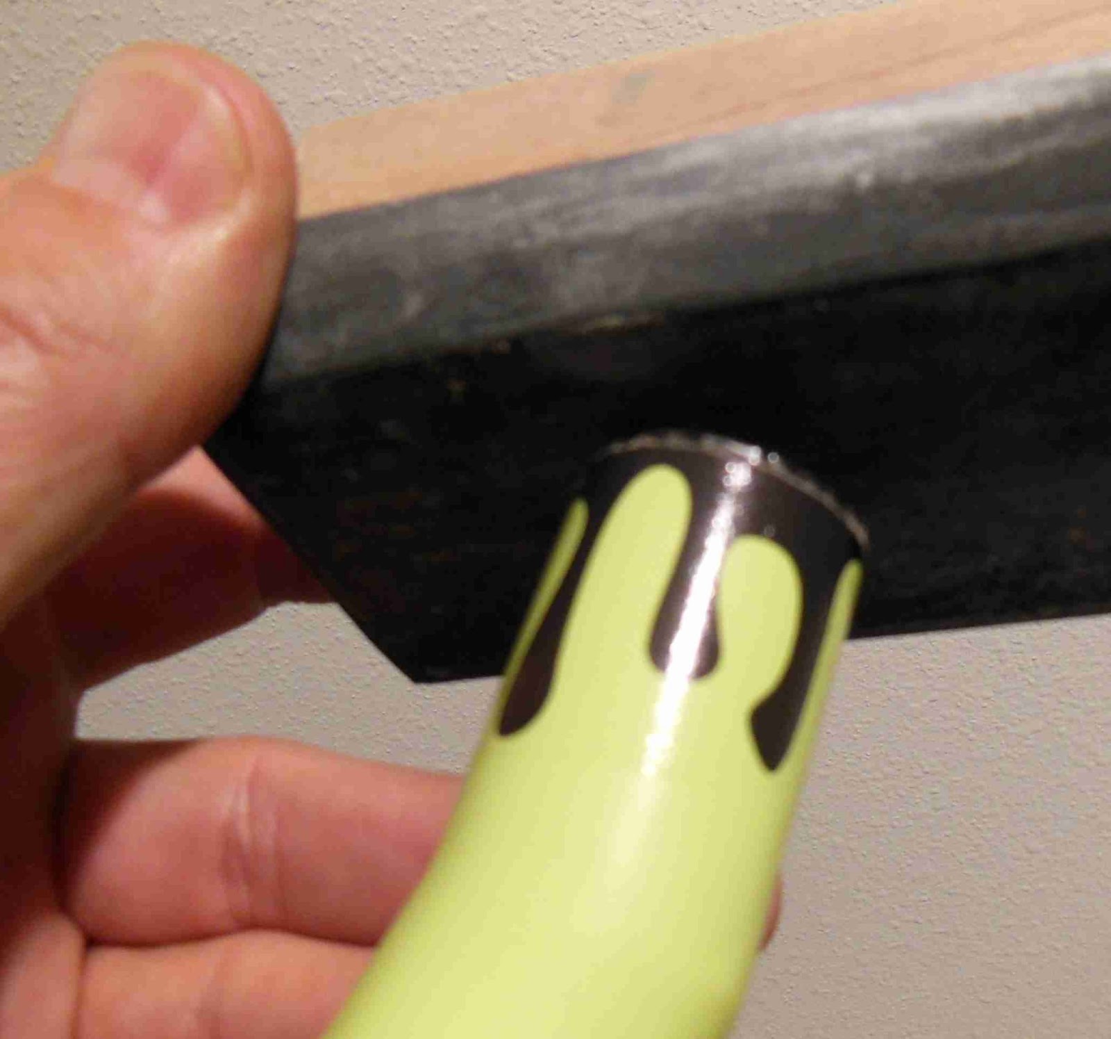
Tube cuts like this would probably work better on a BT-60 diameter model.

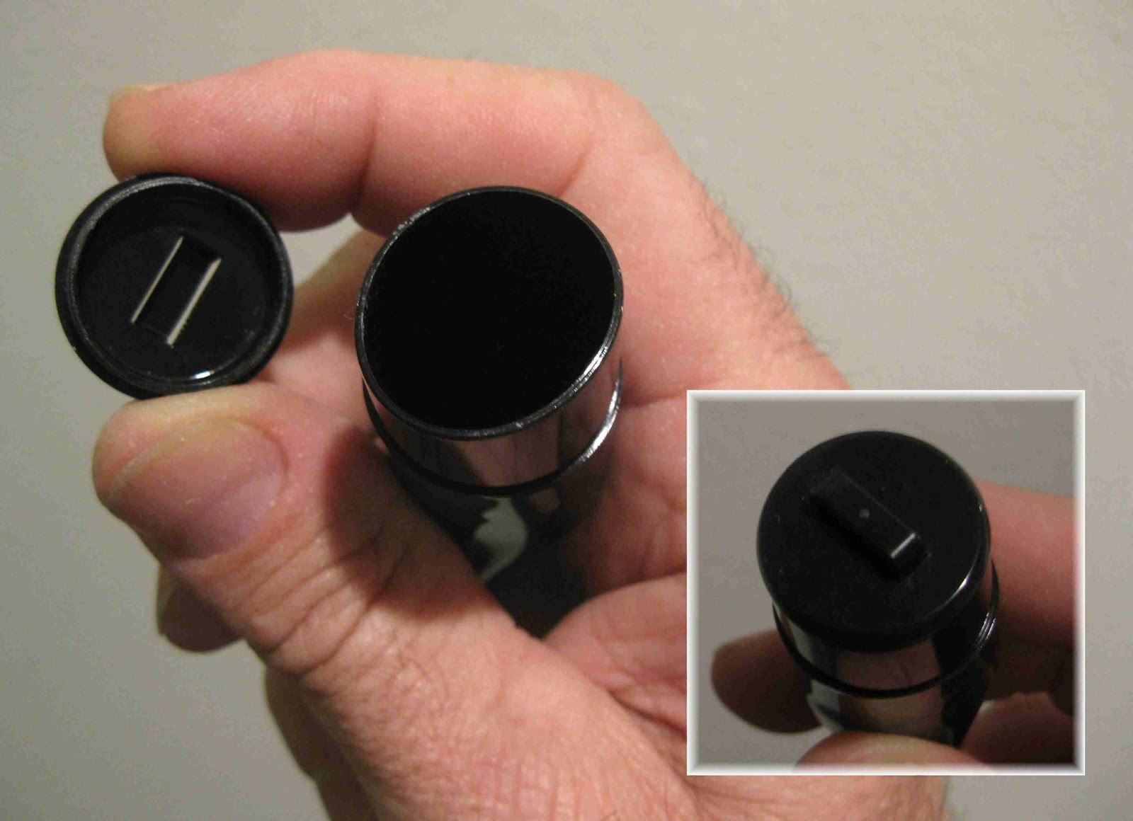
The nose cone is turned so the tip is in line with the center line of the engine mount. If the tip were turned away from the line of thrust it might veer off during boost.
Just to be sure, .20 oz. of clay was added to the inside of the nose cone.
A 12" parachute was clipped onto the shock cord, down a few inches from the nose cone base.

Now - to see if it's stable!

Update: The "Warped" rocket did fly at the February Tampa TTRA launch with an A8-3.
It's stable and flew well with no wiggles or rolls.

Monday, March 11, 2013

Warped! Part 9 Decals and Shock Cord Mount


I drew and printed a decal wrap to look like stylized drips.
This will go along the top of the body tube to tie in the black nose cone.


The wrap was applied with the black edge even with the edge of the body tube. This left a clear border overlap.

After the decal drys you can either cut the edge off with a razor blade or sand it even with a sanding block. Don't sand it flat, angle the block and sand from the outside to the center all the way around the edge.


The lime green color lip was showing with the nose cone in place.

Grab your Sharpie and carefully run it around the edge to blacken the green paint on the tube lip.


I didn't attach a Kevlar line to the upper centering ring on this model.

I was concerned that the Kevlar line would snap hard against the bend joints in the body tube.
I ended up using a standard tri-fold mount made from 100 lb. card stock.
The tri-fold mount was glued right over the top joint to reinforce the "bend" even more.

Sunday, March 10, 2013

Warped! Part 8 Primer and Paint


With the first coat of primer I could see how smooth the joints were.
I was a little surprised, they came out better than I thought they would.
This one took two coats of primer, sanding after each coat.

I had an old can of Rusto 2X, a horrible Key Lime Pie green.
It seemed appropriate for this rocket.

No pics of the fins being glued on. They were stepped, the first fin at the base of the body tube, the other two slightly higher.


The nose cone and one fin were painted gloss black.
You'll see why when the decals are applied.

Saturday, March 9, 2013

Warped! Part 7 Fins and Decal


The original fin design from the Zero Gravity are unusual.
This elliptical shape would still work with the "Warped" name with some subtle changes.

The first top fin shows the kit orientation.
Fin two will simply be flipped over (I know, balsa grain and all)
The third fin get the root edge trimmed turning it's leading edge up a bit.
I went to a favorite FREE font website called:
www.1001freefonts.com

I went under the "distorted" section and found a great font called "To Forgive". This font looks a little melted and fits the and "Warped" name.
You can always type in your models name in a preview window to see how it'll look.

Friday, March 8, 2013

Warped! Part 6 Joint Filling


All the segments glued up - 

I did brush over the joints and seams with CWF.
Sanding followed and then another coat of CWF.


Primer followed.

A few of the joint seams show very slight cracks.
I'll hit them with some medium CA and sand with 400 grit.
I'll probably need another coat of CWF and more sanding after that.

Thursday, March 7, 2013

Warped! Part 5 Tube Joint Reinforcing


Small strips of paper were cut to make reinforcement tabs.
The pieces were cut from paper a bit thicker than a standard 20 lb. copy paper.
Here's what you are shooting for -
This picture only shows two of the four strips glued in place so far.
I went back and glued four more between these for eight in total.
That's eight pieces in each tube joint.

It's important to glue on one segment, then the eight reinforcement pieces. Then move onto the next higher body tube segment.

After trying a few different ways to glue the tabs, I found the following to be easiest:

Apply some glue to the tab location using a Q-Tip.
Using long tweezers, set the tab into the glue and over the inside of the joint. Glue the other seven tabs in place.
After all tabs are dry apply more glue over the top of the tabs using another Q-tip.
This gives a very strong joint that should hold up well to repeated ejections.

Warped! Part 4 Tube Joining


Stacked up, here's the body tube segments.
The tops and bottoms of the segments were numbered 1, 2 and 3 on one side and
A, B, C on the other.

Notice the bottom segment is longer, that will hold the engine mount.


The engine mount was glued in the lower, longest segment.
The engine block is pretty close to the top of the angled tube.

Normally I'd use Kevlar through the top of the mount centering ring.
I was concerned about the Kevlar line hitting the tubes and possibly breaking a glue joint at ejection.

Later, I'll add a tri-fold mount with an elastic shock cord.

Starting from the bottom and working up, the first segment was glued in place.

The joint was rolled over and smoothed a bit with the back end of a Sharpie barrel.

Only glue the first segment on for now, you'll have to go inside and reinforce the joint.

Wednesday, March 6, 2013

Warped! Part 3 Body Tube Cuts

I honestly didn't know if this was going to work, but worse case, I'm only out $2.00,
So with a new razor blade I tried to cut and "warp" the body tube -


Draw a pencil line down the length of the body tube for a center reference. Directly opposite this line, draw another one down the other side of the tube.


Wedge shaped cuts were made it the tube.
The pencil line is out of view, at the center and top of the wide part of the wedge.
After this first cut is made, stop and mark both sides.
One side gets marked 1, 2, 3, the other side A, B and C.
You should mark the tube sections, they are easy to get mixed up!


The cuts were squared up on 220 grit sandpaper on a block.

Check the next blog post to see how the tube pieces are marked.

Warped! Part 2 Nose Cone

The shoulder of the nose cone was out of round, but with the base inserted it is round enough to fit in the body tube with no problems.

Someone at the launch suggested the warped nose cone looked like a Jalapeno pepper. It did.
I looked online for images of peppers, but they were short.
I could print up red, yellow and green peppers and stick them on down the body tube. The nose cone would be the 3D topper on the rocket.
But that's the easy way out, the body tube would remain straight and only the nose cone would be bent.
It could also be a snake head - nah!

I decided to make the entire rocket a little "warped". Nose cone, body tube and fins.
And, it's got to be stable.

Tuesday, March 5, 2013

Warped Part 1 Parts

I picked this one up at the February Orlando R.O.C.K. launch.
It's originally a Custom Rockets Zero Gravity kit.
I saw it in a "bargain box" at the jonrocket trailer for $5.00.

But, something was wrong - 
Take a look at the nose cone -
Somewhere down the line it was subjected to heat and warped!
The bend starts about halfway down the nose cone.

I showed it to Roger and he said: "$2.00!"
Heck, for the parts alone that's a great price. I bought it, warped nose cone and all.

The parts of interest:
Of course, the warped nose cone.
1/4" elastic shock cord seemed thick for a BT-50 based model.
The Die Cut balsa fins. (I thought all kits had laser cut fins these days.)

The other parts were of high quality, the BT-50 was better than many I've seen in recent Estes kits.
I like the Custom line of kits. Good quality at a reasonable price.
Now, what can I do with that nose cone?