Showing posts with label Instructions. Show all posts

Wednesday, May 8, 2024

New Estes Mini Alpha Instructions - Shock Cord Mount


The new Estes Mini Alpha kit instructions have been posted online: CLICK HERE

Most instructions tend to say tie a "double knot".
This implies tying two overhand knots which gives you a "granny" knot. They are prone to slip and open up. Unless you were a Boy Scout, a first time builder probably doesn't know the difference between the two knots. 

At the arrow point in the illustration, look how short the free end of the shock cord line is! If you've tied a "granny" or "false knot" that short end could easily pull through. Tie so the free end is longer, maybe 3/8" to 1/2".

You can use fancier knots, but a "square knot" is easy and shouldn't come undone when tightened.
In the third picture below, note how both ends come out side by side. Both lines come out under the turned line on one side and over on the other side.

Instruction once said to use a drop of glue to "set" knots.
If you tie and tighten a knot correctly it shouldn't need the glue.

TIP: NEVER, no, no NEVER apply super glues (CA glue) to a knot!
CA dries hard and makes the shroud line or shock cord brittle. 
If you want, you could apply a small bit of white or wood glue to a knot. Again, if you tied a good knot correctly, it won't need the glue.

I tie parachute shroud lines using square knots. In the past, some shroud lines found in Quest kits would come undone by themselves! Those Quest lines did require a small drop of white glue to help hold them closed.

Monday, January 10, 2022

OOP Semroc Kit Instructions List

On the Rocketry Forum, 
Tigerhawk posted a list of Model Rocketry part vendors.

I knew most of them, but one did catch my eye.
The old Semroc website no longer exists, but a link to OOP Semroc kit instructions is still available.


It's a great source for those wanting to build a few  classics.

Wednesday, July 14, 2021

Plan Ahead - The Tazz Engine Mount #7282

There's a good reason why instructions say to read them all the way through before starting construction. Sometimes you have to make adjustments. Dry fit everything before squeezing out any glue!
   
The engine block and centering ring placement on the Estes Tazz instructions can be confusing. 
In the instructions the engine block (Part B) isn't butted up against the upper bend of the engine hook. If glued as shown (even with the tube end) there will be a 1/4" gap between the hook bend and the block. You want the engine block touching the top bend of the hook otherwise the hook could get loose after a few flights tearing into the tube.

The instructions show the centering rings glued directly over the 1/2" and 2" marks. There isn't a side view drawing to double check things.


If the rings were glued over the pencil marks there wouldn't be enough space between them for the supplied 1 1/4" wide streamer. Sure, you could cut down the width, but I'd rather have as much descent drag as I can get.

Dry fit the parts before using any glue on the rings. Use the streamer width to set the space between the rings. The upper ring will end up higher, closer to the top bend of the engine hook.

Saturday, March 27, 2021

TLP Hawk Build, Part 1, Parts Pack Instructions

This looked to be something different.
I found a The Launch Pad "Parts Pack" instruction booklet with most parts on Ebay.
A vendor may have bought old TLP instructions and pieced together tubes, centering rings and sheet balsa. Or - 
This may have been a early transition kit produced by TLP. 


Here's the parts pack instructions cover.
I wrote down the recommended engine designations after looking them up on the old Launch Pad website.


If you were to make the model from scratch (no pre-made tubes) the instructions explain how to roll them from manila paper or cardstock.

The main body is made up from smaller segments, joined by DIY couplers. The kit I bought included a two longer body tubes and a standard coupler. The vendor assumes you will use the body tubes.


Here's the nose cone "witches hat". You have to transfer the measurements and cut it out of cardstock.
The supplied parts included a BT-80 Alpha style plastic nose cone.
A pointed cap is rolled from cardstock and glued to the top to lengthen the plastic nose cone. The extension give the nose cone a more correct profile. Seams and joints are filled and smoothed over.


This detailed page shows the conduit shaping and decal placement.  Decals aren't  included in the TLP kits. A disappointment to some builders as kit face cards imply full markings.

Monday, February 15, 2021

Semroc Instructions -


Insane Rocketry has posted many of the Semroc Instruction PDFs on their website:

CLICK HERE


Saturday, August 17, 2019

Ashasta-Sadie Instructions Are Back!

Maybe they never left?
My older address didn't work anymore -
Now the kit instructions are hosted by Blues Rock

PAGE 1
PAGE 2

Scroll down for the plans -

You might find a few instruction sets that are not hosted on Jim Zs or Old Rocket Plans.

Thursday, February 21, 2019

Mistake in Estes #1969 Saturn V Inter Stage Wrap? Part 1

On the NAR Facebook page, Jay M. Chladek may have found an error -
If the wraps are aligned (as molded) and shown in the instructions, the vertical half round wood tunnels may not line up between the Inter Tank and Inter Stage vacu-form wrap locations!

"ALERT: There is an error with the S-1C to S-II wrap as designed by Estes. The details on the S-1C part of the main wrap are clocked over by one position. The four sectors on the Saturn V are labeled Positions I, II III and IV. The S-II and Inter Stage part of the wrap from left to right starting at the seam are Positions II, III, IV and I. Unfortunately the details on the S-IC part of the wrap from left to right are Positions I, II, III, and IV. To fix that, I had to cut the S-II part of the wrap off the model after I had applied it! But I got it fixed and it didn't require much repair (thank goodness)."


"This is a scan from the instruction sheet showing the wrap as it appears in the kit. The problem isn't evident until you apply the wrap. If the modification is not made, it is amplified when the lower S-IC wraps are added as they help to align the two tunnel rails. If you don't reposition the wrap, you now have a tunnel rail going down the gantry swing arm side of the rocket and the umbilical port on the middle S-IC wrap is now sitting in a completely wrong sector."


"Here is the fix. It is easy to do, especially if you haven't glued the wrap on yet. Cut the wrap at the S-IC to Interstage seam, or at the seam below it (which I did to keep from damaging the ullage motor fairings). Then reposition the S-IC part of the wrap. If you do it right, the swing arm umbilical at the top of the S-1C should be perfectly centered directly under the access door on the interstage area. If done properly, everything below should align correctly on the shifted wrap seam while everything above should still align properly on the original wrap seam positions from the S-II on up (with the minor exception of the SII to S-IVB transition which should have the molded in access door also aligning with the swing arms/umbilical attachments as well). 

I contacted Estes about the problem and suggested they make an addendum to the instruction sheet. Whether they will or not remains to be seen. But the fix works and the rocket will be more accurate when done."

I haven't built the new #1969 Saturn V kit so I can't verify the alignment. It sounds like Mr. Chladek found the error and made the correction after noticing the tunnel pencil lines didn't line up! 


The #1969 Saturn V kit instructions are now posted on the Estes website: CLICK HERE
Go to pages 7 and 9 (right side of PDF) to see the tunnels and how they should vertically line up with the molded wrap tunnel locations.

On the left - It looks like they corrected the names on the scale kits page.

Wednesday, November 28, 2018

Ashasta-Sadie Kit Instructions Are Back!


All the archived kit instructions are back on a new Ashasta-Sadie web page.
They were gone for a while, my old links wouldn't bring anything up.

To see all the available instructions: CLICK HERE
http://www.ashasta-sadie.com/

Between the Jim Z's, Ye Olde Rocket Plans and the Ashasta-Sadie sites, most all older kit instructions are available.

Friday, June 1, 2018

Odd'l Rockets F-104 Instructions Omission

I got an email from Gary S. asking for a measurement in the F-104 Starfighter instructions. On the first run of the kit instructions were missing a measurement.
In Step 20, the back end of the intake nose cone half is glued 5 5/16" from the back end of the main air frame tube. Step 20 is shown above.
I've sold quite a few of these kits and haven't heard from anybody about the omission. Sorry for any confusion! If your build is a little off, it shouldn't matter. I've seen F-104s fly at club launches with no stability problems.

Thursday, November 23, 2017

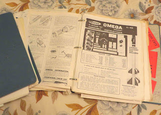
Old Instruction Binders - FOUND!


My Brother-in-law and I have been going through my Mom's house clearing out cabinets and drawers. She was a "child of the depression" and kept most everything. Mom would have never been featured on the show "Hoarders" but she did keep a lot of crap you and I would have thrown away!

At one time I had a binder full of Model Rocket News and correspondence. I did find that in my old bedroom years ago. But - the kit instructions binders were gone!

Maybe not gone, but misplaced in all places, my Sister's old bedroom. Two binders full of kit instructions were buried high above her clothes closet. There are probably 150 kit instructions here, in two binders. I thought there was only one binder.
I will have to go through them and see what might be missing from JimZs and oldrocketplans.com. I'll scan what might be missing and submit them.

The only drag is there are index holes punched and some pencil and pen notations on the sheets. I'll be able to remove most of that. There are no fin templates or decals, we didn't have scanners back then and a young builder would use all that came with the kits.

In the back of the second binder are all my flight records from the first launch in 1969 through 1977.
I don't remember launching my Estes Saturn V, three times with D12-3 engines. But, it's all there in the records. I'm surprised the D13s didn't blow through like they were known to do. (For all you "kids", that's why Estes downgraded the engine to a D12.)


In one binder was a lone 20/60 centering ring, like one you might find in a Big Bertha or a Goonybird kit. It's die-cut and a bit yellowed.
The ring thickness is about half of what we have today.
I'll have to find a build for it.

Monday, April 3, 2017

New Starship Nova Instruction Change

On YORF, John Boren of Estes explained a change in the upcoming Starship Nova re-release:

"This version of the kit is built a little different then the original version. The end result is the model looks exactly the same. On the original version you were told to cut the main BT-50 body tube away to accept the shorter BT-50 tube that in seen on the lower portion of the model. This means the shorter tube is now recessed into the longer main tube. You were then told to add a glue fillet around the joint. Only problem is on the 7 test models I made this glue joint came apart on ALL 7 models from the ejection gases. So now you instead cut the shorter tube so it simply glues to the outside of the main body tube, Problem solved."
                                                                                                           John Boren
_____________________________________________________________________

The older kit produced from 1981 - 1984 was catalog number 1371. The new kit number is number 7262.
If you want to study up for a future build, the original instructions are at JimZs: CLICK HERE

I had never built this kit and was curious about the construction. The new kit change Mr. Boren talks about makes better sense.
On the right is the original instructions. A slot is cut in the main BT-50 tube and a second, smaller BT-50 is glued in the slot.
The ejection charge would hit the low end of the embedded tube!

Cutting a piece out of the shorter tube then gluing to the outside of the main body makes better sense!


Monday, January 9, 2017

Long Tom Fins - The Final Word!

With most all of the JimZ instructions back and available for viewing, I could finally check the Centuri Long Tom instructions to check the sustainer fin placement.


While this step doesn't say the rear of the fins are even with the end of the tube, the illustration shows they are!


Later in the instructions this is shown.
Good, I'll sleep better tonight!

Sunday, January 8, 2017

JimZ's Is Back!

JimZ is Back!
If you don't know this website, it holds many old rocket kit instructions and publications.
Here's the address:
http://www.spacemodeling.org/jimz/index.htm

I understand the address has been changed slightly, so copy the new address shown above for future reference.

For anybody looking to clone a model it is a valuable resource.
Over the past few years some Centuri instructions wouldn't come up. Most recently the website was gone while the DARS section found a new server.


Thanks to Tony Reynolds for taking the time to bring everything back 
and to the NAR DARS Section for hosting the website! 

Saturday, December 17, 2016

Estes Long Tom, Follow-Up - Sustainer Fin Locations?

At a recent Orlando R.O.C.K. launch, Glenn S. launched his Estes Long Tom.
I looked at the fins and wondered why they were positioned up from the end of the sustainer body tube.


On the left is my finished Long Tom. On the right is Glenn's model. Notice the upper stage fin locations?
Glenn said this was his second Long Tom build. He noticed in the instructions that it showed the fins glued on up from the rear of the body tube. His second build had the raised fins.
I read and follow directions and wondered how I could have missed this.

Earlier in the instructions you are instructed to mark the fin locations with a wrap around guide.
No mention is made to make a mark 1/2" or so above the low end of the tube.

The fin gluing illustration in the middle of page 4 shows the two fins marked "J" above the tube. Look at the straight on view of the middle fin. It looks to be even with the end of the body tube.

The inset picture is from a later step in the instructions. The trailing edge is even with the end of the tube. Most all other drawings show the same fin position.

Here's the face card illustration.
The back end of the second stage is black but you can make out the fins are glued on up the body tube.

The Estes instructions are inconsistent. Is it a big deal, does it effect the flight? Probably not.
If you wanted to build it closer to the old Centuri version it's a little maddening.
I went to double check the instructions on the JimZ site but many of the Centuri plans don't come up.

Wednesday, November 2, 2016

Noris Raketen Aggregat - 9, Background

This is the Noris Raketen AGGREGAT - 9.

I'm building this one for a client.
I've seen them on Ebay but never put in a bid. Like the Chinese made MPC rockets, I'm always curious how rocketry is done in other countries.

There's not much available online about the rocket, but I did find this:
The Aggregate 9 (A-9) / Aggregate 10 (A-10) was the last in the Aggregate series of missile designed and developed by Dr.-Ing. Wernher von Braun in 1944 under the leadership of Dr. Walter Robert Dornberger, at Army Research Center Peenemünde.

The Aggregate 9 (A-9) / Aggregate 10 (A-10) was a two-stage intercontinental ballistic missile (ICBM) which design can be traced back to the early 1940s some of the people who assisted in the design were Ludwig Roth, Hermann Oberth, Walter Thiel. However work resumed in 1944, under the codename of Projekt Amerika. The Aggregate 9 (A-9) / Aggregate 10 (A-10) was 26 m long by 4.75 m in diameter and had a take off weight 100 tons and used the following engines first stage 1 × liquid fuel rocket engine producing up to to 30,500 kg of thrust. second stage 1 × liquid fuel rocket engine producing up to to 152,500 kg of thrust. Which gave a maximum thrust of 183,500 kg for 50 seconds of burn time.


There's not much to go on in the instructions and all the copy is in German.
The two pages shown here are specifically for this build. The inside and cover pages are generic looking a little like a condensed Estes Yellow Pages.

Here's the engine mount directions.


Page two shows the fin placement, launch lugs and cockpit locations.
That's about it!


I went to Google Translate and typed in most of the German copy.
Many of the words didn't translate so I'll have to wing it!

The box copy exclaims:
Lehrreich! = Instructive!
Raketenfliegen Ganzjahrig Erlaubt = Allowed rockets fly year round!
Sicher! = For Sure!
Interessant! = Interesting!
Immer Wieder Verwendbar! = Always Reusable!

This should be fun! = Das soll Spaß machen!

Friday, September 30, 2016

Saturn V Blog Posts - Book Form!

Estes has re-released the Saturn V kit - CLICK HERE
The build book PDF is only available to Patreon subscribers.
This new version has injection molded two-piece plastic fins, a big improvement over the two-sided vacuform fins. There are probably other updates in the kit but many of my build posts still apply.

Here's my original blog post from a few months back:  
I received an email from Andy Stobie. He was getting back into rocketry and was interested in buying an Estes Saturn V on Ebay.
I told him to wait, as Estes is coming out with a new version of the 1/100th scale Saturn V kit in late June.
EDIT: After delays it was just released in September, 2016.

Andy had found my Saturn V build posts. The problem has always been that the posts are retained in the dated order, from finish to start. The Saturn V build was LONG, leading to a lot of backtracking to get to the first post.

Andy took the time to put the entire build into a WordPad format, from start to finish!

The blog goes into detail on many steps. There are lots of tips and kit enhancements along with a timeline showing how long each step took.

If you request this "book form" build, please be a serious builder. It takes a few minutes to send the files via DropBox. As explained earlier, this build document goes from start to finish. The original blog posts go from finished build to the beginning requiring some backtracking.

This document is available to Patreon members, email me at oddlrockets@bellsouth.net
and request the Saturn V blog build in DropBox formats.

Many thanks go out to Andy for taking the time to put the build in an easier format!

Wednesday, August 3, 2016

Centuri Mercury Redstone Tower Instructions

I know, I've been harping about the Estes Mercury Redstone capsule and tower instructions for a while. For an easier tower assembly I refer people to the Centuri instructions on the JimZ website. Those instructions don't come up now. On some Facebook pages people are still having trouble assembling the tower.

When I was first building the Estes MR I printed the Centuri capsule instructions. These cover the correct, easier (upside down) tower assembly, the capsule and how to tie a recovery sling that allows the capsule to fall tower up under a separate parachute.
The Estes instructions have you glue the tower sides (right side up) into the dimples in the antenna housing. Centuri has you first gluing two tower sides together. The tower sides are upside down. Then align them top down using the inverted escape motor bottom piece.

I took pictures of the instructions, I don't have a scanner right now. These were copied at twice my normal resolution for the blog. Enlarge them and they should be easily enough to follow.
For large, easiest viewing - Right click, then "Open link in new tab". Open the new tab at the top of the screen.


Wednesday, April 20, 2016

Mercury Engineering 3" Diam. School Rocket Now Available!

Here's the first page of the instructions I produced for the
BMS Mercury Engineering 3" SCHOOL ROCKET

To see the kit: CLICK HERE Look for "School Rockets" along the top of the first page.
For the instructions: CLICK HERE
The kit is now available and worth waiting for. A blog build of this model will start in a few days.
A great value and great demonstration rocket for only $14.95!

If you need instructions produced for your rocket kit, contact me at: oddlrockets@bellsouth.net

Wednesday, March 9, 2016

FSI Viking 3


I was on the FSI Facebook page - CLICK HERE
and came across a picture of the Viking 3 kit tubes.

I never owned one of these kits but was curious about them.
These tubes look like they were cut on a band saw! Pretty rough and could be cleaned up with a sanding block.
Still, if I received these parts in a kit, I would have been disappointed. I'd rather get a wrap, trace it and cut them myself.

To see an example of FSI instructions, CLICK HERE

Friday, January 15, 2016

New Estes Little Joe Instructions are Online!

I was surprised to find the new Little Joe II instruction PDF on the Estes website this morning:
CLICK HERE

It usually takes a while for new kit instructions to be posted. For all those waiting for their kit, this could be some good "pre-build" reading.

Step 2 has you remove a 1/16" section from a short length of tube. The third illustration shows it is glued on the outside of the tube. The ring will support the raised band at the rear of the wrap. (Thanks to Rick Randol for the correction!)
The double thickness centering rings (Part E) have cut-outs to keep the weight down in the back end.
Six pats of clay nose weight are included. Some goes in the upper escape rocket, more is pressed into the top of the capsule.
The rubber shock cord is tied to a notch in the upper centering ring of the engine mount.
There are LOTS of plastic detail pieces (Parts L, M, N, O and P) shown on page 3.
The parts illustration doesn't show the water slide decal sheet.
Painting direction is vague. From all I've read, chrome paint is difficult to use. The instructions don't say if the corrugated section is painted silver or chrome.
The do say a clear coat can be applied. A clear coat could dull the metallic finish.
A single 24" parachute is used. I would probably go with the 24" chute on the body and a 15" on the capsule, tied so it lands with the tower pointing up.
Check out page 10 and 11 of the old Centuri instructions for how to rig the Command Module parachute: CLICK HERE
Referring to the more detailed Centuri instructions might answer any questions regarding the CM and tower assembly. (The CM and tower are from the old Centuri molds.)
15 to 16 squares of wadding? The body tube is 3.4" diameter.

Yeah, I know, I'm being picky. I don't even have the kit in my hands.
Looking at the instructions, these are some points that might help out those first builds.