Showing posts with label Controller. Show all posts

Tuesday, December 29, 2020

New Micro Clips

Along with my new heavy gauge blast deflector - I decided to replace my micro clips. 

Copper is a better conductor than the steel clips included with my 6 volt Estes controller. 
I found them on Ebay, four for $4.95 plus shipping.
Copper micro clips were on my original Electro Launcher from 1970.
I prefer the flat jaw clips, not the larger alligator clips with the jagged teeth.

If you bend your igniter ends out away from the nozzle, you can connect to the side and outside the engine nozzle flame. These copper clips could last a long time.

Note in the right side picture the spring relief on the red wire out the top of the yellow controller. The wire exiting the top of the controller is a weak point in the design, the wire can wear and break.
To see how to install the ball point pen spring - CLICK HERE

Monday, May 4, 2020

Fixing The Estes Launch Controller, Part 4


From the charger cable fix link from the last post:
I grabbed an old ball point pen with the spring over the top end of the ink barrel.
To get the spring started over the lead wire, the top of the spring was opened up slightly.
This took two tries to get right so be patient -
On the left is how not to get the spring around the wire.

The right shows the wire being surrounded by the spring. Be sure the open end of the spring is continuing around the wire. The opened end of the spring faces down toward the controller box.
You'll have to spin the spring quite a few times to reach the end.


You could cut off the micro clips, slip on the spring and re-solder the clips back on, but this way seemed easier.
On the left the spring is completely over the red wire.
In the right, I lifted out the relief knot and slid the spring close to the knot. I didn't turn the spring into the plastic box, but simply pressed the wire and spring end inside the exit hole area.


Here's the finished fix!

As mentioned before - 
Don't wrap the thin red wires tight around the plastic controller box.
Roll in loose loops keeping the wire at the exit hole without a sharp bend and tension free!

Sunday, May 3, 2020

Fixing The Estes Launch Controller, Part 3

A comment from the Estes Controller Fix posts:
"Have you considered opening up the hole in the end of the case, and adding a short section of heat-shrink over the wires as they come out of the case for a little extra stress relief? Don't know if it would work, but it sounds good anyway!"
Sincerely,
J.W.

An email from Brian Coyle,
"Saw your post about fixing the Estes launch controller.  Reminded me of this USB hack & I wondered if it might help reinforce the cable where it enters the box.
To see the article: CLICK HERE
Since you are removing the cable from the terminal, maybe even a section of heat-shrink tube could be added. (Alone or over the spring)"

Thanks Guys!
For the heat shrink to work it would have to extend into the exit hole in the plastic controller box. That would involve making the hole diameter larger. Not a problem to enlarge the hole. There is just no room inside the top of the controller for a little of the shrink wrap with that strain relief knot tied in the wire.
But, the spring might work if the end were turned into the hole - 
See next post . . .

Monday, April 27, 2020

Fixing The Estes Launch Controller, Part 2


Notice the knot, it ends up inside the plastic casing wall to provide some strain relief.

I used the old cut off end to set the correct distance from the end for the new knot.
About 1/4" was stripped off the ends exposing the bare wires.


The wires were soldered onto the contact plates.

The plates were pressed back into the housing, the knot set just inside the wall.


New alkaline batteries were installed.
The back cover screwed on.

To test the controller -
Clip the micro clips together. Insert the safety key, the continuity light should come on.
Press the launch button, the light should go out.
Release the launch button, separate the clips.


Check your micro clips.
If they ends are bent, you can flatten them with smooth pliers.


Here's a launch controller up for auction on Ebay.
Notice the red lead wires wrapped tightly around the body of the controller. The wire out the top is sharply bent and wearing against the plastic exit hole.


TIP: Always wrap your lead wires off the controller body. Leave the wire at the top loose with no tension where it leaves the controller body.

TIP: I applied a square of red tape on the launch button. It makes things a bit more interesting than just the overall yellow plastic.

Saturday, April 25, 2020

Fixing The Estes Launch Controller, Part 1

I probably have four Estes Electron Beam Launch Controllers. I also own a Quest and a BMS Mighty D controller.
I typically use a 6 volt Estes or the 12 volt BMS controller at the schoolyard soccer field launches. The Estes controller needs a repair every few years.

Here's where the launch failures can start.

Where the red lead wire exits the controller body, the insulation can wear. The interior wires are thin and too many flexes can break it.

On the left, the two screws were taken out, the back plate lifted. The batteries were removed.


The "L" shaped cover piece was glued on. I had to pry it off using the screwdriver of my pocket knife.


These are the two contact points that will be worked on.


Pull the metal plate off, straight up with pliers. It'll take some wiggling to get it off. The wire will come with it.


The contact on the left side is held in place with a small Phillips head screw.


I'm certainly not a electrician!
Hold the metal parts with pliers when they are heated with the soldering iron.
Place the soldering iron tip on the solder. When it melts, pull the old wires free.

Sunday, January 29, 2017

New Orlando Area NAR Section, ROAR #795

The newest Central Florida NAR Section #795 had a launch scheduled for Saturday, January 28. A burn ban postponed the actual launch but an informational get-together was held. I took a trip over to the site near Christmas, Florida to say Hi and check out the launch site. I got the grand tour from Adam Nehr, his wife Barbara and Matt Fonseca.
While the ROAR Section will host LPR launches, the original focus was directed towards future aerospace engineers, SEDs, teachers and enthusiasts. Larger rockets can follow a launch protocol with extensive data analysis.
Without a doubt this is the most sophisticated launch control I had ever seen.

That's Adam in the launch control center. This is an interior shot with everything built into his pickup bed.
A former experimental pilot, Adam has done photo and film analysis for NASA. His past work as an engineer and machinist came into play constructing controllers, launchers, video, a weather system, radio network, data tracking and even a remote fire extinguishing sprinkler.


The low power pads have baking pans serving as blast deflectors. Each launcher has flight angle control.

The inset picture shows an extended wire "first activation switch". When the rocket leaves the pad the switch activates the flight timers in the L.C.C.


The gantry on the mid power tripod launcher is interesting.
When remotely pulled back before launch, a string is pulled, a magnet released and the video camera is started. (See inset picture) No more long still videos or dead batteries while waiting on the pad!
Matt demonstrates a tool for freeing a rocket stuck high up in a tree.
The slingshot launches a lead weight tied to the fishing line and reel.

The next R.O.A.R. launch is scheduled for February 25.

Friday, January 13, 2017

Centuri Professional Firing Panel

This is the launch controller I wanted back in the early 1970s.
The Centuri Professional Firing Panel - CLICK HERE

It had an aluminum case, a safety key that turned and a red arming light. This wasn't just a "controller", it was a FIRING PANEL!
But . . . at $14.95, I could buy a few rockets and engines. It wasn't a necessity, I already had working Centuri and Estes controllers.

These pictures were posted on the Yahoo! Old Rockets group by ez2cdave. Thanks Dave!
From the outside the controller looks simple and sturdy. You can see the black "crackle" finish on the aluminum case. 

Opened up, there's not much there. For $14.95 I was expecting more! These were probably assembled by hand, one at a time.

On the left of the brown cord is a strain relief knot inside the casing.


ez2cdave also posted the first page of the Centuri instructions.

Wednesday, September 28, 2016

D.I.Y. Launch Controller Housing?

After a few years in the hobby, this is the controller I wish I could have had. Even as a "Lone Wolf" flyer I wanted the best.
The Centuri Professional Firing Panel, $14.95 in 1972.
It had a safety key you inserted and turned to make contact. The housing was aluminum.

Most of the project boxes available today are plastic. At one time Radio Shack carried an aluminum box, but most of those stores seem to sell cell phones now.

Last year I bought some Alto Sax reeds and guitar capos from Banggood.com.
Both were very cheap, sent from China. Quality was just okay, the guitar capos were knock-offs of American designs, not the same quality as those made in the USA.

Banggood sends me occasional emails and these caught my eye.

These Aluminum Project Boxes could work well as D.I.Y. launch controller boxes.
Aluminum isn't hard to drill through and is certainly much stronger than the thin plastic boxes. These "Stomp Box" cases are meant to sit on the stage floor and hold stronger switches that are hit with your foot.

The middle sized "B" size box measures 4.4" L x 2.5"W x 1.3" H.
Price is $8.99 with free shipping.
To see the listing, CLICK HERE

Sunday, August 21, 2016

Old Launch Controllers on Ebay

Here's an interesting Ebay listing: CLICK HERE
A real collector might be interested in these -


The first controller looks like the Centuri Professional Firing Panel.
For the Centuri catalog listing, CLICK HERE


This controller looks like the original "Spring Return Safety Switch" contact switch used in the earliest Electro-Launch systems.
To see the catalog listing: CLICK HERE

Thursday, March 19, 2015

Mystery Controller?

Here's one I can't identify - Does anybody know who made it?

It's from an Ebay listing.
It doesn't look like a home built controller, the gold panel inset has printed "Power, Armed, Ignition and Safety Key" wording.
The safety key is interesting. It has a key shape but doesn't look like it turns. It is slid into a slot to make contact.
If you know who manufactured it, leave an answer in the comment section below.


Friday, December 5, 2014

Wrapping Controller Wires?

A very important TIP, After a launch session -
Don't wrap the thin red lead wires tightly around the controller!

Two reasons:
If the red lead lines are wrapped over and depress the launch button while stored, this can bend the inside contacts and leave the button in a down or depressed launch position!

Look at the top of the controller where the red line leaves the controller.
Never put a sharp bend in the red wires over the top of the controller!
Over time the red cover insulation gets stiff and can crack if sharply bent too many times. The thin wires inside also bend and break.

Always leave some slack at the hole where the line leaves the controller case! This simple strain relief will extend the life of the controller wires. The wire does tend to break where it leaves the top hole of the controller.

My controller and red lead lines are loosely set down inside the bottom of my range box.

Wednesday, November 19, 2014

Red Launch Button

I add a red tape piece over the launch buttons on my controllers.
Shouldn't a launch button be red anyway?
The Estes controllers have been a single color for years now. 
I place a piece of colored electrical tape on top of the button.

The old piece was sliding off.
The yellow plastic button has a ridged surface. The tape was removed and the ridges sanded smooth so the new red tape would stick better.

This time the red tape square was cut a bit smaller than the top of the yellow button. Keeping the tape edges away from the button sides will keep the corners from lifting.

This controller is special. It was a prototype model sent out by Estes for customer testing. It was hand wired with a (new for Estes) LED continuity light.

Sunday, August 31, 2014

Battery Life? TIP


I'm changing out a 9V battery in my guitar preamp.
While the owners manual says you can get 100 hours of performance, it never seems to last that long.
To keep track of the new battery life, I marked the install date: 6/11/2014 with a Sharpie


This might be an interesting test for launch controller batteries, especially the Quest controller that also uses a 9V battery. The single 9V battery seems to lose its ignition strength faster than the Estes 6V controller.
You could also mark one of the four AA batteries in an Estes style controller.
If you keep a flight log (recommended, go to www.rocketreviews.com, register and start a flight log) you could keep track of how many launches and in turn, how many batteries you use.

Thursday, August 28, 2014

Old School Controller

From a rocket parts listing on EBAY: CLICK HERE was this do-it-yourself- controller.
This looks like something built from a page in the old Estes catalog Yellow Pages. Note the flip switch continuity and doorbell launch button.

Most of the other items weren't worth bidding on.
It was refreshing to see a simple but effective home-built controller.


Here's another D.I.Y. controller from the 1975 Centuri catalog.

I've always used manufacturer produced controllers.
A few friends made their own. As long as the battery was new they worked fine.

Monday, August 18, 2014

An LED in a Black Electron Beam Controller


Installing an LED in the black Electron Beam is much easier than in the yellow casing.

The picture shows the old exposed bulb and the LED replacement.
A black plastic "dome" lifts up to expose the older bulb.

Turn the old bulb and lift up - That's it!
Set the LED in matching up the tabs with the slots inside.
Give it a quarter turn to lock it in and you are ready to launch.

Be sure to lightly pull up on the LED making sure it is "locked" in place.

Much easier than the Yellow plastic controller.

Saturday, August 16, 2014

An LED in a Yellow Electron Beam Controller

Right after the Quest Q2G2s were introduced -
Some had the igniters fire when the safety key was inserted.

The Quest controller has an LED continuity light, the Estes controllers had an older filament bulb.
The Q2G2 requires less power to ignite. When used with an Estes Electron Beam controller the bulb didn't provide enough resistance. All the new Estes controllers now have LED lights.

JonRocket.com is offering a special on LED bulbs. I picked up two for replacement in some older Estes controllers.

The Estes Electron Beam controller has gone through some changes over the years. The post covers just one of the yellow versions.


This yellow controller has a clear plastic cover over the bulb. It's glued in place and I couldn't remove it from the outside.
The battery cover was removed. All the internal parts are under a glued on cover. It was pried open and slowly lifted with a small screwdriver.

Two more screws were removed to lift the contact plates. In the inset picture you can see the base of the bulb.

There is a strange shaped spacer on the bulb.
Note the shape. The flat side has to fit against the side wall of the housing. The two extended pins fit into notches around the open circle housing.

The LED is slightly higher than the old bulb. To fit in in, the clear cover had to be broken and pulled out. Trim off any remaining plastic if still glued onto the side of the hole.

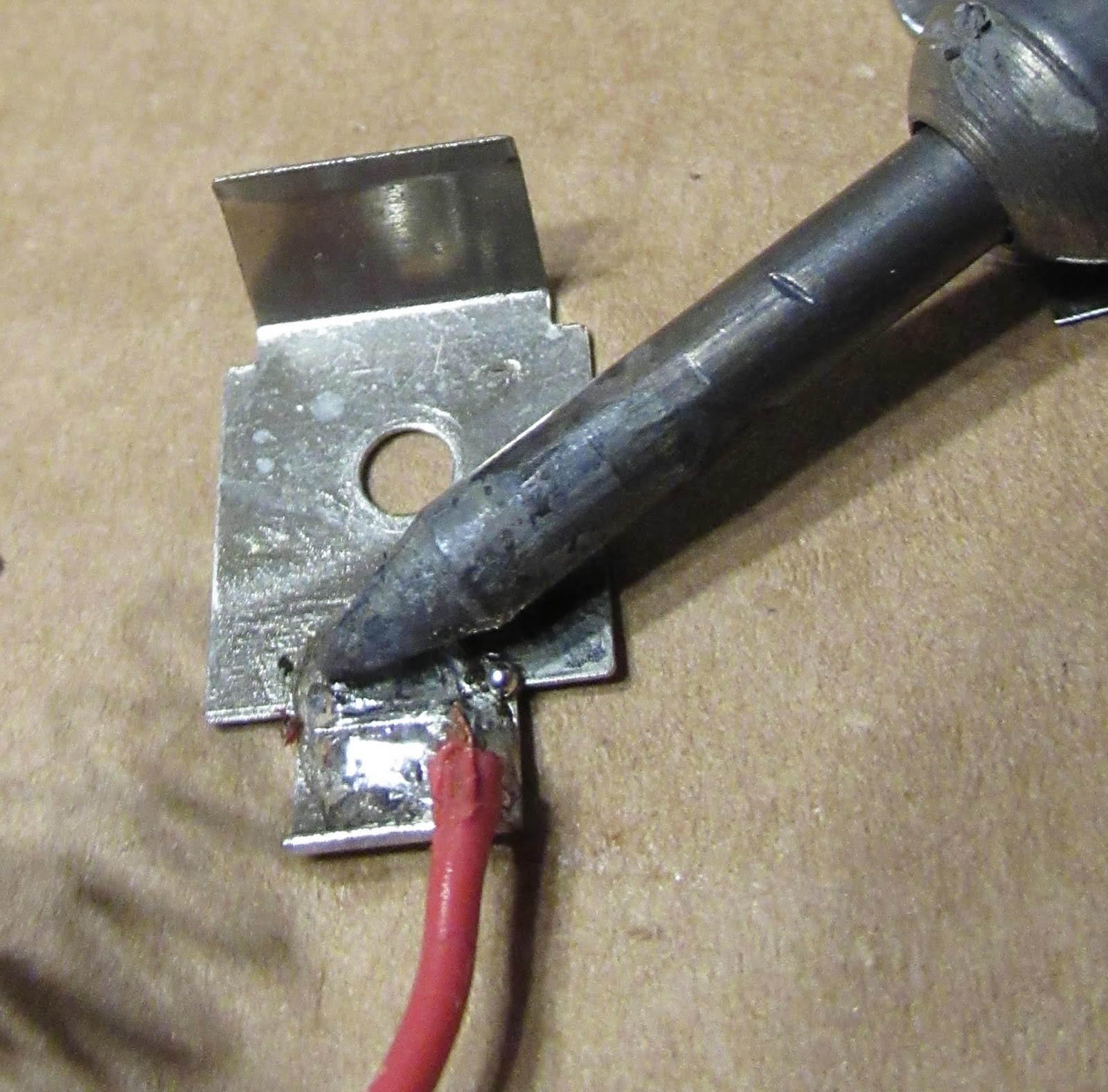
Here's the new LED in place.
It was tested with a Q2G2 with the key in place. The igniter did not fire.

The LED sits a bit higher than the old bulb.
It is very bright outdoors under sunlight.

EDIT: If I were to do this again, I would just cut the top off the clear light cover.
The LED would stick up over the side walls of the dome. The LED light wiggles a bit. Having just the side wall of the clear dome around the light would protect it  from all sides.

The two year old Estes controller I've been using has an LED already in place. It was a test model hand wired at Estes to see if the LED lights would work. 
I added some colored electrical tape trim to the single color, yellow controller. On my current controller, the launch button is red.

Wednesday, August 6, 2014

Centuri Powr-Pad Launcher and Controller, Part 4, Safety Key


The continuity safety key is interesting.
A larger plastic housing holds a standard style safety key.

The Centuri name plate piece glues over the key with plastic cement.
There are two small holes at the top for a string. The key can be worn around your neck.


Here's the finished unit with the key fully installed.

I've always inserted safety keys lightly, just closing the gap between the internal plates.
To fully seat this key against the top of the blue housing, you have to press it in hard so the two brass plates are pressed down and apart.


An old Centuri favorite is the Rocket Positioning Spring.
This was the basis for the Odd'l Rockets Raise Spring.

I learned later on that the Centuri spring was a R/C airplane wheel retainer. It was pressed over wheel set onto a 1/8" wire axle.

I threaded the Centuri spring over the lower half of the launch rod. Even with the rod oiled it was nearly impossible to get the spring on the rod! It was just too tight. The Odd'l Raise springs fit easier and locks on the rod when any rocket weight is on the upper arm.

The Odd'l spring has an added brass tube on the upper arm. The tube prevents the thin wire arm from getting stuck under the engine hook.

Tuesday, August 5, 2014

Centuri Powr-Pad Launcher and Controller, Part 3, Internal Wiring

Unlike the old Estes Electro Launch controller, the wire ends had the insulation already stripped off.
The wire strands are twisted and turned into a "C" shape around the screwdriver shaft.
Twist the wires in the direction that the screw will turn. This way the strands won't separate.

Here's how the wires are connected under the small screws.
Notice the open area on the right side of the top half. Any extra wire folds into this hollow space.
With the two sides joined, the gray lead wire winds around the oval "track" around the outside.


The continuity bulb sockets into place.
The two halves are easily screwed together.
The green cover is pressed in over the continuity bulb.

Monday, August 4, 2014

Centuri Powr-Pad Launcher and Controller, Part 2, Internal Wiring


The metallic stickers are applied first.
The blue plastic housing pieces were washed off first to remove any mold release.
The edges were pressed in place with a Q-tip. I didn't want to take any chance of the ink rubbing off.


A knot is tied in the wire for strain relief. The length of the wire end to the knot is the length of the inside housing wall.


The brass contact pieces are screwed in place but not fully tightened.
The gap between the two pieces in the lower half is intentional. The safety key bridges the gap allows the current to go through the continuity light.