Showing posts with label Antennas. Show all posts

Sunday, August 11, 2024

Enerjet by Aerotech, Astrobee D Build, Part 14, Antennas


Here's one of the antenna shoes.

The metal tube is loose sliding onto the round pin.


Lightly crimp the antenna tube with flat pliers. Any pliers with teeth will mar the smooth tube.

Crimp a bit and check the fit. Continue until you get a friction fit on the shoe pin.


The tube should have a friction fit on the antenna shoe for display.

The tubes are removed for flight.

Friday, August 9, 2024

Enerjet by Aerotech, Astrobee D Build, Part 12, Antennas & Launch Lugs

There are mold marks that should be filled.

Sand down the high spots, the low circular dips remain.

I mark the depressions with pencil


The flat back side needed a small bead of CA filler. 

The round depressions easily hold a small drop of CA glue. These CA bead fills take a while to dry. 


Here's what left of the pencil mark and dried CA after sanding with a block. The dimple is filled and the pencil won't be seen under the silver paint to come.


The square 1/4" launch lugs are molded in black plastic. 
I wish these were molded in white, they'd be easier to paint. 

The sides aren't perfectly flat, as some light sanding shows on the left. Sand flat with 400 grit on a block.

Sunday, August 4, 2024

Enerjet by Aerotech, Astrobee D Build, Part 8, Launch Lug Rail


Sand a consistent angle from the smaller top plate, down the middle bar and onto the lower plate. 

Some of that "skin" left under the top plate will have to be lightly filed off.


Defining the rounded taper on the lower plate, I wrapped sandpaper around a 24mm engine casing.

Notice the pencil marks over the front end.

Rubbing some pencil gives you a high contrast surface while sanding. You can better see the width of the sanded edge.


Here's the completed piece ready for the gold paint.


 As it always seems to go - 

Paint shows imperfections. I had to sand some of the mold marks and rough leading edges. More gold paint to come.

Saturday, August 3, 2024

Enerjet by Aerotech, Astrobee D Build, Part 7, Launch Lug Rail


Here's where we are - 

The front angle has been block sanded. It is still a little long.

The top and bottom front (arrow points) are cut with a hobby knife. 

Looking at the bottom - 

Some of that curve will happen automatically from the curvature of the bottom plate. I found I had to sand a bit more to define the curve.

I used a piece of 220 grit wrapped around a spent 24mm engine casing. After the 220 grit I followed with 400 grit.


The bottom after sanding in the front curves.
 

Friday, August 2, 2024

Enerjet by Aerotech, Astrobee D Build, Part 6, Launch Lug Rail

A "T" shaped length of plastic is supplied to make the scale launch lugs. This is one of the more difficult steps in the build.
The instructions say to use either a knife or razor saw to cut two pieces 1 15/16" long. I tried a knife but you might have better luck using a fine point razor saw. 

I cut my two lug pieces a little longer than directed and sanded to the correct length using a block.


On a separate piece of paper, a bottom and top template is supplied.

Set the back end of the template even with the rear of the lug pieces and trace the cuts with a pencil.

Notice the bottom pencil line has a chevron shaped curve. Some of the curve happens automatically because the bottom of the lug is curved to fit the body tube.


Again, I cut a little long and will sand to the correct length and shape.

The front angle is cut with a razor saw.

Wednesday, April 13, 2022

Estes EAC Firecat #0821, Build, Part 11, Final Decals & Loose Ends

You've got to cut up the Bandit decals to get the Firecat to look like the face card.

These are the remaining four vertical black rectangles, cut in half. 
Place these on the white side of the body, directly over the rectangles on the BT-48 roll wrap.

The remaining horizontal bars (seen in the first picture above) are cut in half and set behind the U.S. AIRFORCE decals. Because they are short, they won't reach all the way around.


Here's the view from the bottom.
My balsa nose cone was ordered from BMS, #BMS50HJ.
There was a hole in the bottom center, no drilled dowel was supplied or would fit in the small hole.
I was concerned the screw eye wouldn't "grab" well in the center.  
Simple solution - Set the screw eye to the side. Turn it so it won't hit the inside body tube wall.


FIX:
I didn't get good paint coverage on the trailing edge of the vertical fins.
I used a red Sharpie to fill in the red. NOTE: This doesn't always work! Try a small area first. It can fill well on narrow areas like the flat trailing edges of  a fin. It will not work on flat, larger areas.


I forget to paint the toothpick antenna.

It was taped to a dowel, hit with a gloss white coat.
Smooth sanded after drying and sprayed again.

Saturday, April 9, 2022

Estes EAC Firecat #0821, Build, Part 7, Sub-Assemblies


The BT-48 tube had it's seams filled - the seams you'll see anyway. 
The front and rear of the end joint and spiral seams were filled.
The area in the center will be glued onto the balsa standoff covering most of the seam.


The raceway was painted with some CWF. While it was still wet - The Antenna was slipped into the drilled hole, turned to round out the hole then removed so the CWF could dry.


The instructions don't mention rounding any of the fin edges, but the drawings show them rounded.

After doing some dry fits I realized rounded leading edges would leave gaps at the front corners. (See inset picture) I decided to leave them square.


Here's the wings, raceway and intake/engine glued in place.

Notice the back "step" placement of the small wing tip. A very creative kitbash.

Friday, April 8, 2022

Estes EAC Firecat #0821, Build, Part 6, The Raceway Antenna Slot

The toothpick Antenna is optional. Before drilling a hole, consider this: 
The balsa is 3/32" thick and the hole is tricky to drill. It's something an ejected parachute could get caught on. Decide if you want to tackle the detail.

Use the Raceway pattern to get an idea of the antenna angle. 
Set the template next to the balsa raceway and pencil mark where the antenna hole will be.

I used a small rat tail file to get the hole started.
The file was spun, the angle checked.

The hole was widened using the tapered end of a (un-sanded) rough toothpick. Spin the toothpick, then use the file.
It's easy to crack or swell out the sides of the soft balsa raceway. Go slow - 


The toothpick is smoothed out.

The end that will be glued into the raceway is also smoothed and tapered a bit so sides of the raceway won't bulge out.


Here's the antenna in place. The angle match is good.
Look close at the side of the antenna wall. The side collapsed a bit and that dip will be filled.

I'm not going to glue the antenna into the hole. The antenna will be slid into place for display and removed for flight. 
TIP: This is like the antenna spike on the Mercury Redstone tower. The old Centuri instructions recommend not gluing it in place. Press in place for display and remove for flight.

Friday, January 1, 2021

Estes Saturn 1B, #7251 Build, Part 34, Antenna Gluing


I still have a paper wrap around the body for protection while handling.

The antennas are set to the side of the glue area and a pencil line is drawn. Do the same on the right side - draw a line inside the right side of the antenna.


Carefully scrape off the paint down the pencil line.
This scraped line is inside the let and right border edge of the antenna pieces. If you scrape outside the the final antenna position, you will have some tricky paint touchups.


Once again a line of Beacon Fabri-Tac glue was set down the sides of the antenna back. Don't use too much glue or it might squeeze out on the sides when pressed into position.

The more you look at the tough masks, the more touchups you realize are needed. I did more cleanups.


Build time:
Glue antennas: 30 minutes
Additional paint touchups: 15 minutes
Total build time so far: 26 hours, 40 minutes

Tuesday, December 15, 2020

Estes Saturn 1B, #7251 Build, Part 18, Tunnel Mask & Capsule Tower Paint

The Antennas have raised vertical yellow bars. I wasn't sure about masking these, they would be a bear to hand paint. I figured I'd try to Scotch tape mask them

Scotch tape is set on a plexiglass, black Sharpie lines are drawn down the strips. The black edges are needed to see the clear tape on the surface borders. 

Before applying the marked clear tape to the model, wipe off any excess ink with a paper towel so it won't transfer onto your fingers or the model.  


This took some time and quite a few tape strips.
After the black tape was set down, brown masking tape covered the outside areas. 

Before painting, the edges were pressed down using a Q-tip.


These really turned out well, one of my favorite parts of the build.
When masking on a smooth surface, the edges come out sharp and clean.
The Command Module and tower were spray painted Gloss White separately. This is too be sure I get paint on the top of the command  module. If the tower were glued on, the paint wouldn't get under the struts.

The tunnels were also sprayed gloss white. The entire model will get a shot of clear flat after the decals are applied.

Build time:
Prep Tunnels, Tower & Antennas: 25 minutes
Mask & Paint Antennas: 45 minutes
Total build time so far: 12 hours, 5 minutes

Thursday, August 20, 2020

Centuri Flying Saucer #5325, Part 7, First Fit of the C Braces


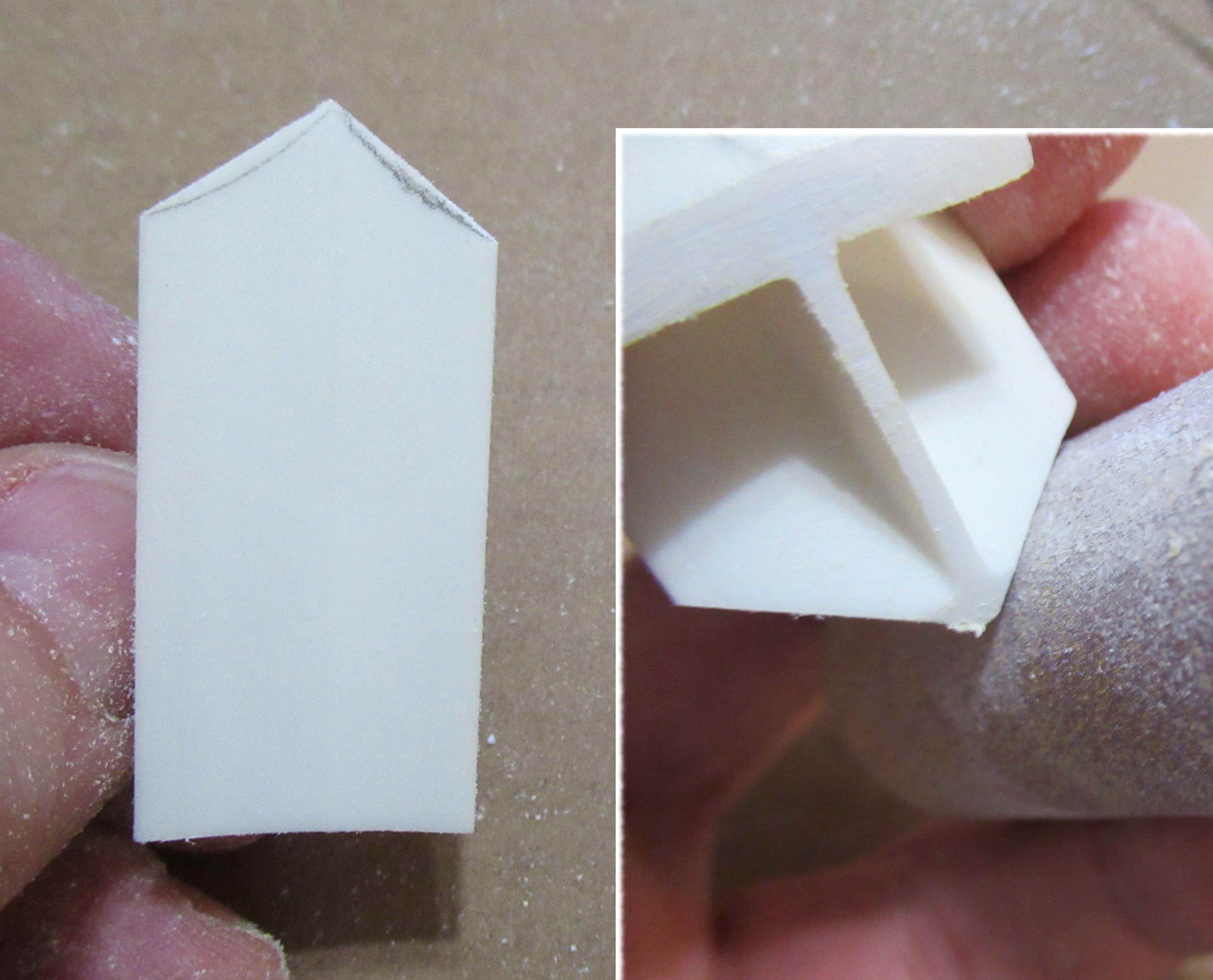
TIP: You can get a rounded leading and trailing edges on carded fins by applying a glue bead down the edge. Apply a fine line of glue, then run your finger down both sides of the fin to even out the glue bead. Let dry and sand lightly with 400 grit.

This glue bead will also strengthen and seal the edges of the fins.
I tried to slide the engine mount assembly into the center core. The fit was too tight!
With the addition of the wire thickness the span was now too wide! I trimmed off about 1/32" from the outside edge of the C brace.

I later learned this wasn't enough! You'll have to trim off almost 1/16" for the proper fit.
I'll continue with the build to show what happened - but be aware, on my build it required some extra fitting and time.

I made some "Wire Form Retainers" from 110 lb. card stock. These were just strips of card stock about 3/8" wide.

On the left it looks like a simple fold. The center is actually a double fold, to roll over the wire antenna positioned in the center.

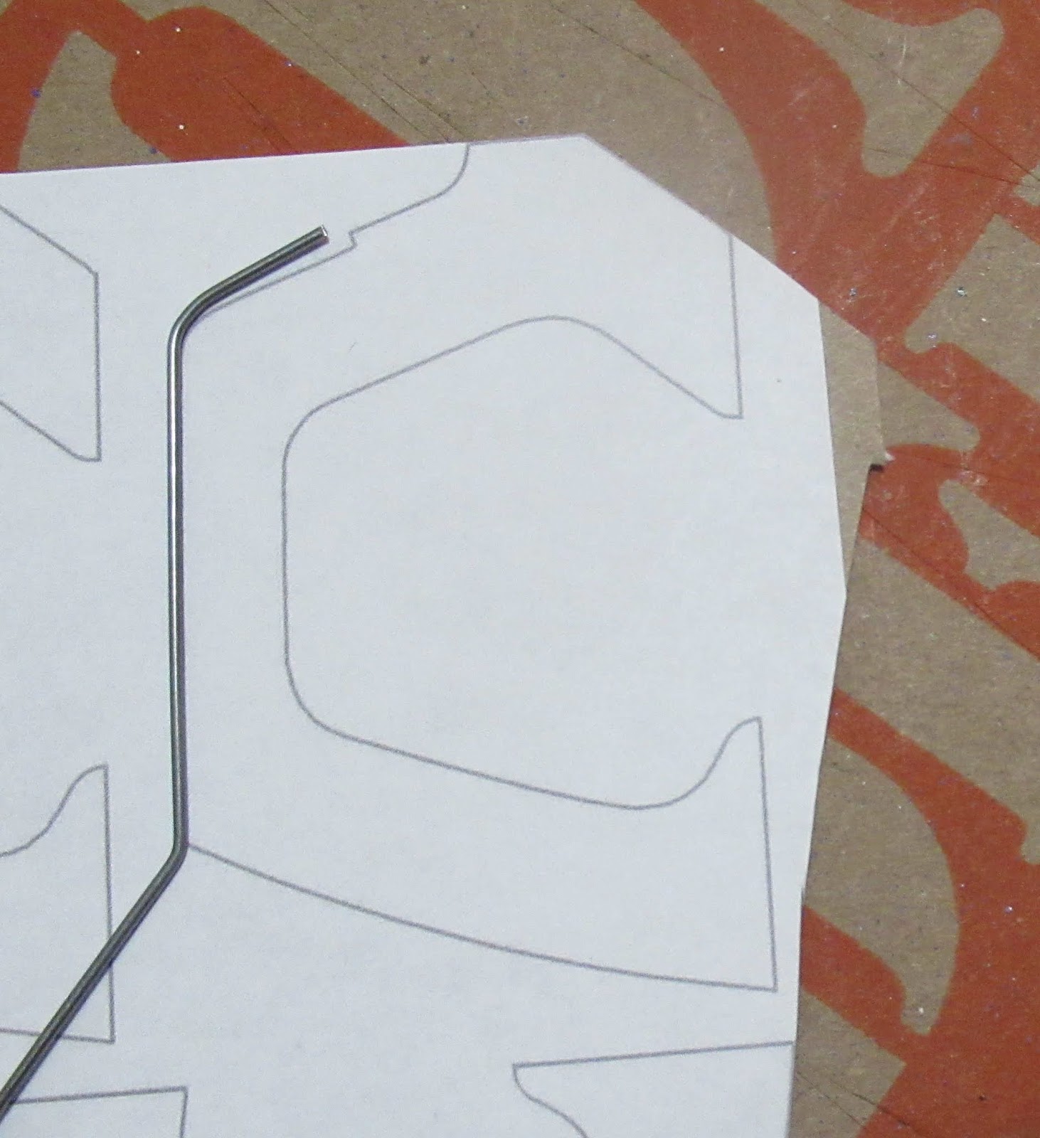
I drew up some Wire Form Retainers along with an Antenna Template. This PDF is available to Patreon supporters. Email me at oddlrockets@bellsouth.net and ask for the Centuri Flying Saucer PDF.
Note: I do not have all the templates, just the 75% size antenna and the antenna retainers. All other PDFs for the main body parts are listed in the first Background Post: CLICK HERE


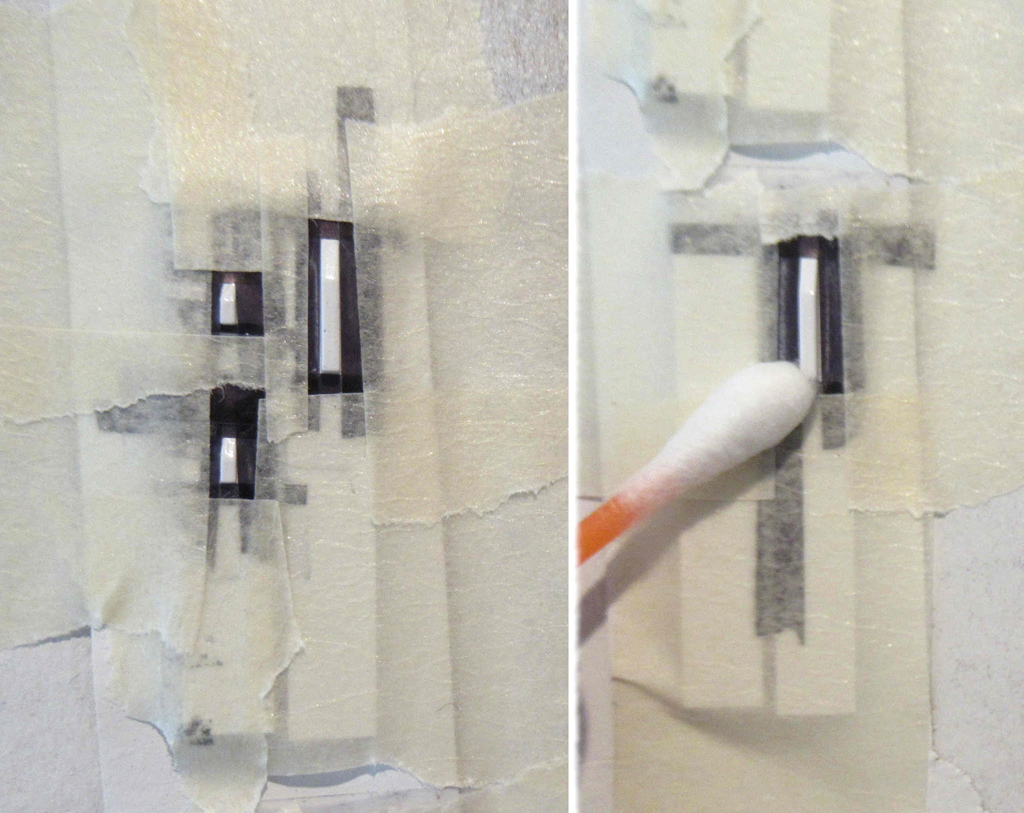
Here's how the antennas fit -
And the retainer strips over that. That angle joint at the upper right is cut and fitted.

When first gluing on the antennas (left picture), don't use much glue. They hold better when the glue is about half dry and tacky.

Sunday, August 16, 2020

Centuri Flying Saucer #5325, Part 4, Wire Antennas

The instructions had a print of the original kit antennas. Since this is a 3/4 size downscale, I drew a 3/4" box and reduced the 1" span box to the 3/4" length.
Below the print are the three finished, bent antennas.

You'll need some music wire. I found some at Hobby Lobby - K&S wire, #602201, #5497, .039" diameter.


I tried bending the outside round circle shape around a dowel, but wasn't successful.
I had better luck with needle nose pliers. Don't try to bend in one movement. Make many small bends around the circle shape. Check against the print as you go.


Keep the circle bend flat. It's very easy to have it end up going out to one side.


The bent wire matched the template print.
I set it on the 75% size "C" shape brace. The upper bend needed to be a bit sharper.
Notice the end of the wire, it is shorter than the notch allowance. I made the notch a bit lower to fit the end of the wire.

The antenna wire and reinforcement piece template is posted in Frank's build at YORF - CLICK HERE, Page 6, Post 51

Monday, September 2, 2019

New Estes Black Brant II, Changes Part 2, Antennas

In the previous version of the kit, you surface or end glue toothpicks to the outside of the upper body tube. It's recommended that this antenna assembly be used for display, you were given another length of BT-55 without antennas for flight.
These 1" long toothpick antennas could break off very easily.

Be careful if you drill the antenna holes with an X-Acto knife tip. The diameter of the hole can easily end up too large. Spin drill a little, check the fit then repeat. You want the tube hole to fit fairly tight around the antennas.

In the new kit you are provided with plastic tapered toothpicks. In the instructions, the end is cut off leaving a 2" length. The second picture shows the ends being glued to the tapered base shoulder of the nose cone.
(Don't the antennas cut to length yet - Read the next paragraph)

GOTCHA: The 2" long plastic toothpick antennas don’t touch the bottom of the nose cone shoulder as shown in the instruction drawing. The nose cone shoulder doesn’t go down far enough to contact the toothpick base ends. 

Left Picture: With the toothpicks extending 1" outside of the body tube section (using the 1" measurement from the previous BBII kit instructions) the toothpicks cross and hit each other inside the tube. With the ends inside ends crossed up it effects the angle of all three antennas.
Right Picture: If the toothpicks are cut to 1 11/16" the ends will touch and give you a triangle center gluing point. Place a drop of plastic cement where the three ends meet. When glued at the center you should end up with the proper downward angle and exposed length outside the body tube.


Here's the finished antenna/body tube segment. 
At the 1 11/16" length, the toothpicks will extend 1" outside the tube.

Friday, August 16, 2019

Estes Sasha Build #7271, Part 10, Antennas Glue & Fill


This is not a necessary step, but you know me!
I had to decide which would look better, rough glue fillets on the joints or a smoother surface transition.

Some thinned CWF was dragged down the joint similar to how I'd normally fill the body tube seams.


On the left is the CWF after sanding with 400 grit.
On the right I've dabbed on some filler primer with a Q-tip for a final fill.


Here's the upper stage fins, antennas and filler smoothed.
All eight fins are ready for gluing on the upper body in the next post.