Showing posts with label S Point. Show all posts

Sunday, December 12, 2021

Follow-up Letter To Semroc About The POINT Build

Here's a copy of the
correspondence to Semroc and
Randy's note to Phil in Semroc R&D - 

Hi Randy,

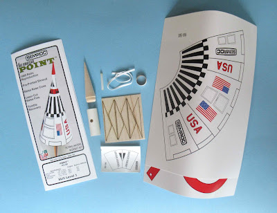
I'm doing a build of the Semroc POINT kit for the blog. 
I wanted to give you a heads up - 
There are problems!

* The holes punched in the motor mount tube are too low!
The holes punched at the center should be higher up on the tube so the ejection charge hot gas will escape above the top edge of the main body shroud. 
Where they are now, they could char the inside of the shroud.
Not really a problem, I have some ST-7 tubes. I cut and punched a new tube.

Here's where the real problems lie - 
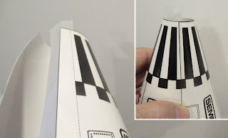
* The shroud print is smaller than the original kit shroud.
The outside edge of the angled fins will not correctly contact the inside of the shroud.
This sets the mount too low inside the shroud.
The base rings do not fit the base of the shroud.
They might fit if almost 1/8" is cut off all the way around the base disk.
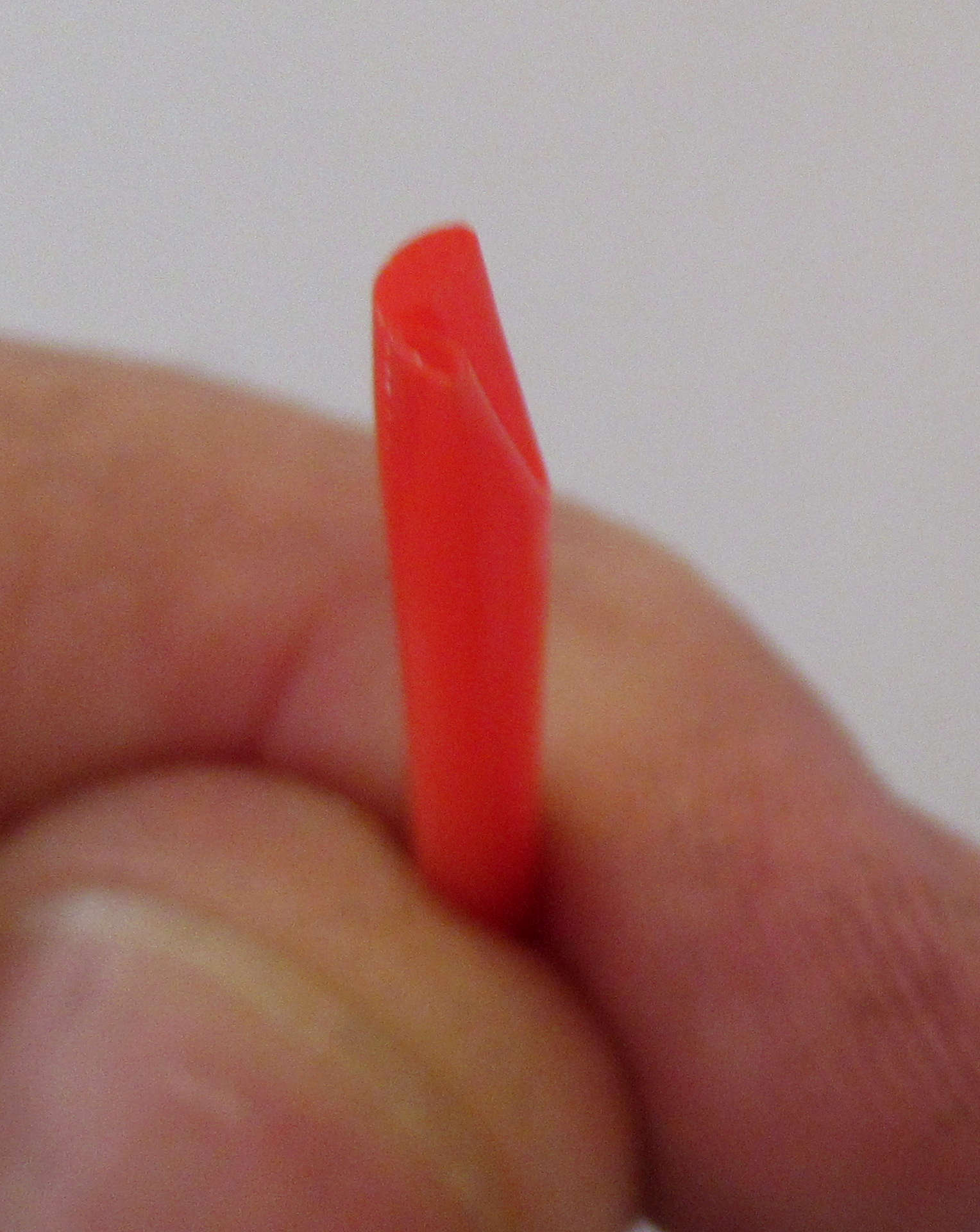
The vertical red ring had to be cut down to half it's height (now 3/8") to fit the shroud.

I hope you didn't have many of these printed, I know these things can happen.
Anyway - not complaining, I've had to do some revisions in my kits, too!

Happy Thanksgiving!

Chris Michielssen 
Odd'l Rockets 
______________________________________________________________

Response from Randy at ERockets/Semroc - 

Ouch,
It looks like the tool was made wrong for the punching the tube, all of our inventory is bad, this likely happened 2 years ago when we made duplicate tools so each SKU would have its own.  

The shroud is the wrong size and we have been printing from the master all this time, this last batch I could not get our printer to print on the correct paper so I sent it out to be done.  But it came back exactly like the master.  So I don't know when we went bad on this part.  I think this is the key reason the kit is not going together correctly.

The red ring has always been that size, not sure if it was a mistake Carl made in the design or if he did that on purpose.

Based on the proportions the inside red ring does not line up correctly.  Sure, if the Shroud is not right this is not going to fit.
 
The canopy wrap looks like it was always wrong, I think it is better to be slightly larger because the cones can very in diameter slightly so it needs to have some give.  The same problem existed on my kit made 10 years ago when Carl had Semroc.
_______________________________________________________________

Notes from Randy to Phil in Semroc R&D - 

Phil,
I started cutting parts up on the kit I placed at your desk.  Could you please build one of these and make the needed corrections.  Hopefully, the originals are in the development folder.  I am also leaving you my kit that was built about 10 years ago, it has an astronaut signature on it so please handle with care.

I am removing this kit from inventory until the needed corrections are done.  I am fixing the tool for the tube punching now, and will destroy the wrongly punched tubes too.  I am leaving it to you to make the other corrections.

Respectfully,
Randy Boadway
______________________________________________________________

Semroc is fixing the kit!

What conclusions can be drawn? 
Too many different computer formats can produce different size prints.
Have you ever reproduced something from an online source to find out
you didn't adjust the PDF to print full size? 
I worked in a print shop for years. Things happen.

In my experience producing kits and Accessories, mistakes were made. 
Some vendor errors: 
received an order for 2,500 Raise Springs, all were wrong!
An order of 100 custom balsa nose cones were the wrong shape.
Half an order of Ceramic Blast Deflectors were unusable and had to be thrown away.
Even the largest rocketry vendors had a run of 10,000 kits including a very wrong part.
A part was been missing in a short run of Odd'l kits. Thank goodness it was only a run of ten kits!

I've been there, we've all been there.
Before you complain on a forum, give the vendor a chance to make it right.

Saturday, December 11, 2021

Semroc Point, KV-58 Build, Part 9, Fitting the Shroud?


With the inside taped down, the outside edge of the shroud is still open.
I set a small drop of white glue on my knife. 
Work the glue as a thin film covering all the glue tab from top to bottom.

Close the end and burnish to set the tab.

Here's when I realized something was wrong.

On the left - 
This is as far as the internal engine/fin assembly would go, up inside the shroud.

On the right - 
You can see light at the top of the outside fin edges. Fin contact with the shroud is only at the bottom.  
I figured I could fix it by sanding down the low end of the fins. I don't remember doing any adjustments like this on my two previous Point builds.

This is where I stopped the build -
I guess I could have finished it, but the trimmed bottom support ring was so short the shock cord tie point was removed to get it to fit. I was concerned about the strength of the cone. 

I wrote to Semroc and explained the problems.
The email responses are in the next post.

Why do build posts on a kit that wasn't finished?
Hopefully there are some ideas shown that might help on a different design.

Friday, December 10, 2021

Semroc Point, KV-58 Build, Part 8, Support Ring & Main Shroud


The vertical ring is glued inside the base ring.
Apply glue lightly. Set the ring in place.
Let dry with a wide, light weight on top.

Apply glue fillets afterwards. Go light on the fillets, too much glue can pucker the cardstock.


Keep forming the dowel until it is near closed without any pressure on the outside.


I did my usual pre-forming by pressing a dowel around the shroud while it was sitting in the soft heel of my left hand.


Scotch tape is set down the edge with the sticky side out.
Use the tape to line up the edge lines. Press the tape in place to hold the shroud closed.

Thursday, December 9, 2021

Semroc Point, KV-58 Build, Part 7, Shroud & Support Rings

The shroud is cut out using scissors on the curves.
Cut the straight lines with a knife and straightedge.

Run your finger around the curves and you can feel some high spots.
Curl some 400 grit sandpaper around your finger and lightly sand around the inside curve top.

You can sand the outside (larger bottom) curve with a block.


TIP:
Instead of cutting corners in the square on the inside ring, try using the rotary punch.
A round punch will be much stronger than sharp corners that can tear.


Go slow when cutting out the support ring.

Again, use fine sandpaper to smooth out any rough edge cuts.
After a dry fit, I realized the ring I formed was too tight.
I pulled apart the glue joint (it was still wet) and slightly spaced out the glue tab contact area.  

This moved the alignment of the previously punched shock cord tie holes. I re-punched the hole through both layers.
Maybe I should have punched the hole once, after the red ring ends were glued together.

Wednesday, December 8, 2021

Semroc Point, KV-58 Build, Part 6, NC Canopy Wrap


Here's the Cockpit canopy sticker supplied with the kit.
On my original Semroc Point build, the canopy didn't line up well.


Instead of laying down the side edge first -
Viewed from the rear, set the center line of the sticker down the length of the nose cone.
The sides of the sticker were then rolled over.

Notice how things lined up on the back.


It's not perfect, but better than my earlier build.

I did some light scraping of the black line to remove it.
With the line gone, the angle of the overlap isn't noticeable.

Tuesday, December 7, 2021

Semroc Point, KV-58 Build, Part 5, Root Edge Mask & Undercoats


The original Point kit had a short shoulder on the nose cone. This allowed full clearance at the top of the punched holes in the body tube.
In the right side picture - 
I sanded down (well, up) the shoulder so the holes were fully clear.
The seams were filled with CWF.
Primer /Filler followed with sanding to surface.

Thin strips of masking tape was set down the root edge lines for gluing on the fins later.

There are six fins and they are close together. Masking would be difficult.
With the root edges clean, I can paint the fins black off the body, then glue them onto the white body tube. 


TIP: Here's a good example why you need a white undercoat before color coats go on.

On the left is a filled, primed nose cone. Red was shot directly over the filler and primer.
On the right I used a white undercoat before the red was sprayed. 
Colors like yellow, orange and red are somewhat transparent. A white undercoat makes the color coats brighter and less "splotchy".

Monday, December 6, 2021

Semroc Point, KV-58 Build, Part 4, Tube Punches?


Something about the kit supplied ST-7 tube didn't seem right. On the left is my old Point. Notice where the hole punches are.

They should be very close to the top of the tube. Otherwise, the hot ejection gases would scorch the inside of the shroud.
This wasn't a problem, I still have some ST-7 tubing in the rocket room.

I marked the two opposite hole locations.
Don't just punch holes - 
Initially, use light pressure to make a slight impression in the tube. Remove the punch tool and check to see if the circle impression is centered.

Make any positioning adjustments, then fully punch the two holes.

My assumption was right - these holes would need be positioned higher up above the edge of the shroud.

Understand, I'm not coming down on Semroc. I produce kits and make mistakes. One small run of Break-Away kits was missing fins! I once ordered 2,000 Raise Springs - all were unusable! Stuff happens. 
There is a good outcome in the end.

Saturday, December 4, 2021

Semroc Point, KV-58 Build, Part 3, Parts Prep

The nose cone shoulder lip was a bit rounded.

I painted CWF over the shoulder edge, only on the low end of the nose cone. Keeping the CWF off the top of the nose cone gives me something to hold onto.

Press into the body tube and turn the nose cone. this will leave a raised bead of filler.
After the CWF dries you can sand the new lip even with the sides of the nose cone. That should square up the edge.


The nose cone had a dip in the center. I marked it with a pencil and did another coat of CWF in that area.


The ST-7 engine mount tube had the seams filled with CWF. Filler/primer followed. This was sanded to surface leaving the gray filler in the seams.


The circle punch ports got a light wipe of glue to protect the tube from the ejection charge.

Friday, December 3, 2021

Semroc Point, KV-58 Build, Part 2, Parts Prep


Never just punch out laser cut balsa fins! Note the darker grain stripes in the left side picture. 
Turning over the sheet - you can see the laser cut didn't go through the denser areas of the wood.
I had to use my knife to free up the corners. If I had tried to crack the fins off the sheet, the rear root edge tips would have cracked off. 


I always square up the fin edges being sure the root edge is flat. Fins will glue straighter on the body tube if there is a flat root edge.

The laser cutting beam gets diffused as it goes through the balsa sheet. One side has a wider cut than the other. 


I wouldn't attempt to roll the large shroud with the soft turn in the printed card stock page.

Set the two sheets in a heavy book and let it sit for a few days to flatten the sheet.
 

Thursday, December 2, 2021

Semroc Point, KV-58 Build, Part 1, Parts

EDIT: Towards the end of this POINT build I realized something was wrong. 
I wasn't able to finish it. So, until then - enjoy the ride!
_________________________________________________________________

I have a history with the old Centuri Point.
In the early 1970s, I tried to launch the Point with a B4-2 engine. The Point base is just about the same diameter as the blast deflector on my old Estes Electro-Launch. 
The Bernouli Effect took hold - the Point never left the launcher and ended up in flames. When the instructions tell you to launch with the base of the rocket above the blast deflector, there's a good reason!
I wrote Centuri and ended up getting a new kit and a Centuri B4-2 engine.
Centuri sent an engine through the mail, without a permit - to California!

Years back, I put together a Semroc Point before this blog was started.
Since then it has 6 launches - I might be ready for a new one. I hope to get a cleaner build this time.


The Semroc Point kit is in a larger than normal bag because of the shroud print size.
On the right, you can see the soft curve set in the shroud stock. 


There is not many parts to the kit. The shroud makes up most of the body.
The balsa fins are laser cut from 1/16" thick balsa.
The shock cord is 9 3/4" long.


Parts of interest:
From my two past builds, I remembered how difficult it was to get the canopy sticker to wrap evenly around the nose cone.

That motor mount tube has two 1/4" vent ports, one on either side of the tube. There's a concern with it - more on that later in the build.

Tuesday, November 10, 2020

Prepping The Semroc Point

The Centuri / Semroc Point is a tricky rocket to prep. At ejection the engine is pushed out the back and stays attached to the conical body with a length of elastic.

The engine sits far forward inside the cone body at ignition and boost.

The engine is retained at ejection by a small ring of body tube with a short length of elastic shock cord tied on. Slide it over the low end of the engine. A wrap of tape goes over the low end of the engine and ring.

That elastic tether has to stay out of the engine flame during boost. It is held to the side of the interior wall with a small piece of masking tape.

Before sticking the tape to the cardstock wall, stick it to your pant leg a few times to reduce the adhesion. This will prevent the tape from tearing the interior cardstock when the ejection charge fires.

The engine is far up inside the body and it is difficult to conect the micro clips. The old Centuri instructions suggest using some thin extension wire wrapped around the igniter.

I still have a stash of Quest Q2G2 igniters that are perfect for use in the Point. They have 3" long igniter wire leads.

Quest suggests using the protective plastic sleeve to hold the igniter in the engine nozzle. It helps with the friction fit is you crease the sleeve tip with a fingernail so it fits around the igniter wires.


Here's the back end, the rocket is prepped for flight.

The elastic is out of the engine flame and the Q2G2 is long enough to make the micro clip connection easier.

My Semroc Point has six launches. The rigid chute recovery has worked every time. The rocket is getting a bit banged up, I may have to build another!