Showing posts with label Engine Mount. Show all posts

Monday, September 8, 2025

Estes LTV Scout, Build, Part 4, Engine Mount Gussets

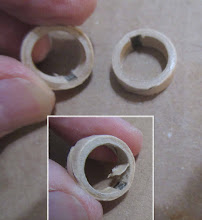
These are probably the thinnest centering rings I've ever run across - The thickness of two layers of 110 lb. cardstock. I've used gussets in the past to beef up an engine mount.
   
I wanted the gussets at a 120 degree spacing or close to it.
A copy paper strip was rolled around the BT-20 tube. Two even folds were made giving three gusset positions.

Wrap around the tube and mark at the folds and where the strip meets.


This is why I save excess balsa left over from other kits.

3/32" thick balsa strips were cut to fit between the two centering rings. These were made a little wide to be sanded even with the outside ring edge after the glue dries.


Here's the final, finished engine mount. 
It's always surprising how much stronger gussets make the mount feel.

This shouldn't be considered "bulletproofing" a LPR model. Just some lightweight strengthening.

Sunday, September 7, 2025

Estes LTV Scout, Build, Part 3, Engine Mount


The engine block was installed just above the engine hook slot position using a glue ended dowel.

The engine hook had a slight reverse bend in it.
I bent a gentle curve to better retain the motor.


The instructions mentioned a hold down strap on the pattern sheet (back of face card). There wasn't one.

No big deal. I used a wrap of electrical tape which would last longer than masking tape.

A drop of wood glue was set over the upper bend of the hook.


The finished mount. Those rings are thin!

The upper ring is set down about 1/8" to allow a glue fillet on both sides.

Saturday, September 6, 2025

Estes LTV Scout, Build, Part 2, Engine Mount

The low inside end of the engine mount tube got a swipe of CA glue. The edge also got a wipe of glue.

Sand the glued end square with 400 grit.

This end will be exposed, it is not a glued surface. The CA glue seals and hardens the tube end.


The engine hook slot cut is made in two steps.
Note the blade is flipped over making two small joining cuts.

Stab and make about half the cut.
Turn the blade over and complete the cut from the other side.


The two facing cuts give you a slot with squared ends - less chance of a tear.

For whatever reason, Estes didn't include an engine block in this kit. I added one.

Thursday, July 31, 2025

Centuri Skylab Build, #KB-4, Part 3, Making A Centering Tube

From the original instructions:
There is a side Kraft centering tube set over the engine tube and engine hook.
I don't have a 3/4" long centering tube, so we'll "make" one.


Three 20/50 centering rings will be used, stacked and glued end to end.

For tighter glue joints, sand the ends flat.


Slide the rings over a BT-20 tube and glue just the rings together, don't glue them to the tube yet. 
Sliding the rings over the tube is for a true, straight alignment. 

The first picture shows how little glue was used.
After the glue dries, slide the three glued rings off the tube.  

The diameter of the centering rings will be too small for a good fit in the BT-52 tube.

Using a glue stick, I wrapped some cardstock around the rings to build up the outside diameter. The ends were then sanded flat.


Here's a good fit in the BT-52 tube.
Don't glue the engine mount in place yet -

Wednesday, July 30, 2025

Centuri Skylab Build, #KB-4, Part 2, Parts Fitting


The 3" long BT-20 tube is notched for a standard engine hook.

The inside of the nozzle doesn't have a relief slot for the engine hook.


A square diamond file cut a notch for the hook.
Don't go too deep, the top of the nozzle is thin.


I marked the inside notch with pencil so you can see the fit through the plastic.
I can now slide the nozzle over the engine mount tube without distorting the tube.

No glue yet, there are more pieces to dry fit.


Monday, July 7, 2025

Estes Mini Bomarc Clone, Kit #TK-5, Part 3, Engine Mount


The original kit instructions don't mention it - 
I did have to cut a relief notch for the engine hook. Here I've marked it with pencil.

The burrs inside the rings needed some light layer peeling to fit over the BT-5 engine mount tube.


I don't like using a tri-fold mount in smaller diameter tubes so I laced some Kevlar below the upper ring. After pulling tight, a glue fillet will lock it in place.


The lower ring slides up to 1" from the bottom of the BT-5 tube.

The upper ring is even with the top of the tube.


There wasn't an engine block in the original kit. I added one.

Slide in place against the upper bend of the engine hook, then add a glue fillet and smooth with a Q-tip.


Also added was the new heat shrink tubing slid over the first four inches of the Kevlar line.
This is butted up against the top of the centering ring and hit with a heat gun.

After heating, the shrink tube ends up tight around the Kevlar line.

Monday, June 16, 2025

Estes AMRAAM AIM-120 Downscale, Build, Part 6, Engine Mount Assembly & TIPS


Many kits have you glue 20/50 centering rings at 1/2" from each end of the engine mount tube. That doesn't really give enough flex for a spring steel engine hook.

The mount shown here is flipped over with the hook pointing up.

TIP: I've found the best position for the low, bottom ring to be 7/8" from the bottom of the engine tube. This allows enough flex to slide in a motor.


TIP: This is a brilliant way to lock in the Kevlar line comes from the older Semroc kits.

The Kevlar line gets a small overhand knot.
This is slipped under the upper bend of the engine hook.

In the picture, the upper centering ring has not been glued in place yet.


The upper centering ring is slid up and glued on slightly over the Kevlar loop.
The centering ring also locks the upper bend of the engine hook in place.

TIPIn all my new builds, I am incorporating heat shrink tubing over the Kevlar line for extra protection. The heat shrink tubing idea comes from Rick Randoll of New Way Rockets.

Wednesday, June 4, 2025

BMS School Rocket, Build, Part 7, Filling The Fin Grain


Here's one side of one fin with the filler brushed on.

Notice I didn't brush filler onto the TTW fin tab.


Many builders comment on forums about how CWF filler warps their  fins.
With the filler on just one side of the fin, the fin will warp as it dries.

Don't worry, the fin will flatten out when CWF is brushed on the other side and allowed to dry.

Tuesday, June 3, 2025

BMS School Rocket, Build, Part 6, Gluing In The Engine Mount & Filling The Nose Cone

I use a dowel set a ring of wood glue inside the main airframe tube.
A dowel is set next to the mount with the end just below the upper centering ring. The bottom of the mount tube will extend 1/4"  below the end of the main airframe tube. The dowel is marked at the 1/4" extension.
A ring of glue is placed around the top of the dowel. Using the pencil mark as a depth gauge, roll a ring of glue inside the tube. 
Slide the mount into place, up to the 1/4" mark.

I like to center the engine hook between two fins.

Right now there is only glue at the upper centering ring.

There isn't much room to apply and smooth a glue fillet around the rear ring. Apply some glue and smooth the fillet with a Q-tip formed into a "tip" by rolling it between your fingers. 


The shoulder lip on the nose cone wasn't as square as I would like.

Notice the CWF filler is painted just over the edge of the shoulder.

Push the nose one all the way into the BT-50 tube and turn.
Turn and remove the nose cone.


What you are left with is a raised filler bead right above the balsa shoulder.
Let dry and sand with 400 grit on a block.

The shoulder lip will end up sharper and a better fit against the end of the body tube.

Sunday, June 1, 2025

BMS School Rocket, Build, Part 4, A New Kevlar Cord Protection?

I can't take credit for this idea - 
Props go to Rick Randall at New Way Model Rockets. He has incorporated this Kevlar protection cover in many of his LPR kits.

Kevlar lines start to break down and can fail at 10 to 15 launches.
Near the low end of the Kevlar, near the engine mount - Rick adds some heat shrink tubing over the Kevlar line. When you consider how hot a heat gun gets (to shrink the tube around a wire) it makes sense!
An black powder ejection charge is momentary, the heat gun take a few seconds to shrink around the Kevlar line.
Heat shrink tubing is not included in the School Rocket Kit. I found some on Ebay and am starting to use it in my builds.

For reference, here's a 1/16" diameter heat shrink tube slid over a 135 lb. LPR Kevlar line.

To fit it over the Kevlar knot under the engine hook,
I flared the open end a bit using a sharpened dowel. The flared end makes it easy to slide over the knot.


On the left,
The heat shrink is slipped down and over the knotted Kevlar line.

On the right,
A heat gun was used to shrink the cover tight over the Kevlar and knot. The hear gun was used on the LOW setting.


There is that square hole left on the other side. Some ejection gasses could escape out of the hole.

A small piece of scrap BT-20 was cut and glued over the hole.

Saturday, May 31, 2025

BMS School Rocket, Build, Part 3, Engine Mount


From the instructions:
This shows a dry fit, the centering rings aren't glued over the laser cut lines yet.
The Kevlar shock cord is tied through a cut hole and around the engine block.
I prefer tying a small loop knot and setting that under the top bend of the engine hook. This is an idea from Semroc. 
More later - 

OOPS! Originally I raised the lower centering ring above the laser cut positioning line to give more flex of the engine hook. I had to lower the ring, it would be in the way of the TTW fin tab.

I set the rings in a light ring of glue, applied to the tube. The ring is slid into the glue ring.


Side by side, 
Here's how the engine mount centering rings set when glued onto the laser cut lines.

You have some good space around the rings and fin tabs.


Wednesday, May 14, 2025

Quest Intruder Kit Bash, Part 6, Shock Cord & Engine Mount Gluing


Here's the finished engine mount with the Kevlar line rolled up inside.

The Kevlar line is pulled out and tied to the elastic shock cord with a simple overhand knot.

Roll up the elastic and Kevlar and push into the motor mount tube before gluing the mount into the main airframe tube.


I used and old dowel to apply the glue into the main airframe tube before sliding the engine mount in.

Set the dowel beside the engine mount just below the upper centering ring. 
Mark the dowel at the end of the engine tube.

Apply a ring of glue around the top of the dowel. 
Insert the glued tipped dowel into the tube up to the pencil mark on the dowel. Roll the glue around the inside of the tube.


Quickly slide in the mount into the main airframe tube.

You can use the flat face of a sanding block to help press the mount tube ends even.

Tuesday, May 13, 2025

Quest Intruder Kit Bash, Part 5, Engine Mount & Kevlar


The Quest instructions use the engine block height to mark the slit cut line. 

Pencil mark and cut the 1/8" wide slot for the engine hook.

The instruction say to glue the two rings 1/2" from the top and bottom of the engine tube.

I don't think that offers enough flex of the engine hook when sliding in an engine.
I set the low centering ring 7/8" from the bottom.


Instead of 1/2" from the top of the tube - 
The upper ring was set over the upper bend of the engine hook, approximately 1/4 from the top of the tube.

I've pencil marked the ring to show how the ring is centered over the hook.
This strengthens the mount. 

The instructions have you tie a double overhand knot to secure the Kevlar under the upper ring. That thick knot might bulge the outer tube - not much room between the 20/50 rings and 1" diameter tube.

I rolled the Kevlar around the tube with the overhang tail twisted under the start of the line. The twisted Kevlar end is pushed into the glue fillet.

Saturday, May 10, 2025

Quest Intruder Kit Bash, Part 2, Engine Mount Tube


I don't know why, but sometimes the Quest engine mount tubes are a little under the standard 2 3/4" length.

The yellow tubes work fine, but seem thin. This tube was starting to peel at the ends.


I switched out for an Odd'l Rockets heavy walled BT-20H tube cut to 2 3/4" long.

I was curious of the weight difference - 

The Quest tube weighed 4 hundredths of an ounce.

The slightly longer Odd'l heavy wall tube weighs 6 hundredths of an ounce.

Sunday, April 27, 2025

New Way Letter - Go Build, Part 5, Engine Mount Gluing

Run the Kevlar line out the back of the engine mount.

I set the engine mount beside the main airframe tube to mark a dowel that will apply a glue line inside the tube. Note the pencil line where the glue will contact the upper centering ring.

Glue was applied to a dowel end and transferred inside the tube.

The mount was slid in with 1/8" of the engine hook exposed out the back end.

A length of heat shrink tubing is supplied to slide over the Kevlar line and down to the top of the engine mount. The tubing protects the Kevlar at the low end from the ejection charge.

To be honest - 
I didn't remember to slide the tube down the Kevlar line!
Here's some shrink wrap on Kevlar before and after being hit with a heat gun.


Considering how hot a heat gun is, the shrink wrap sleeve should give good protection to the Kevlar line 

Roll the Kevlar to keep it out of the way when sliding the mount into place.

The lower centering ring got a glue fillet smoothed out with a Q-tip.