I was waiting to tag these "47"s onto another decal print, they certainly wouldn't take up a whole sheet. I printed these at the bottom of the upcoming Excalibur build decals.
TIP: This is a trick I learned from the Centuri Saturn V instructions. To see it, got to Page 11: CLICK HERE
There are the small A, B, C & D decals on the SV fins. A template is supplied in the kit to give you a visual placement reference.
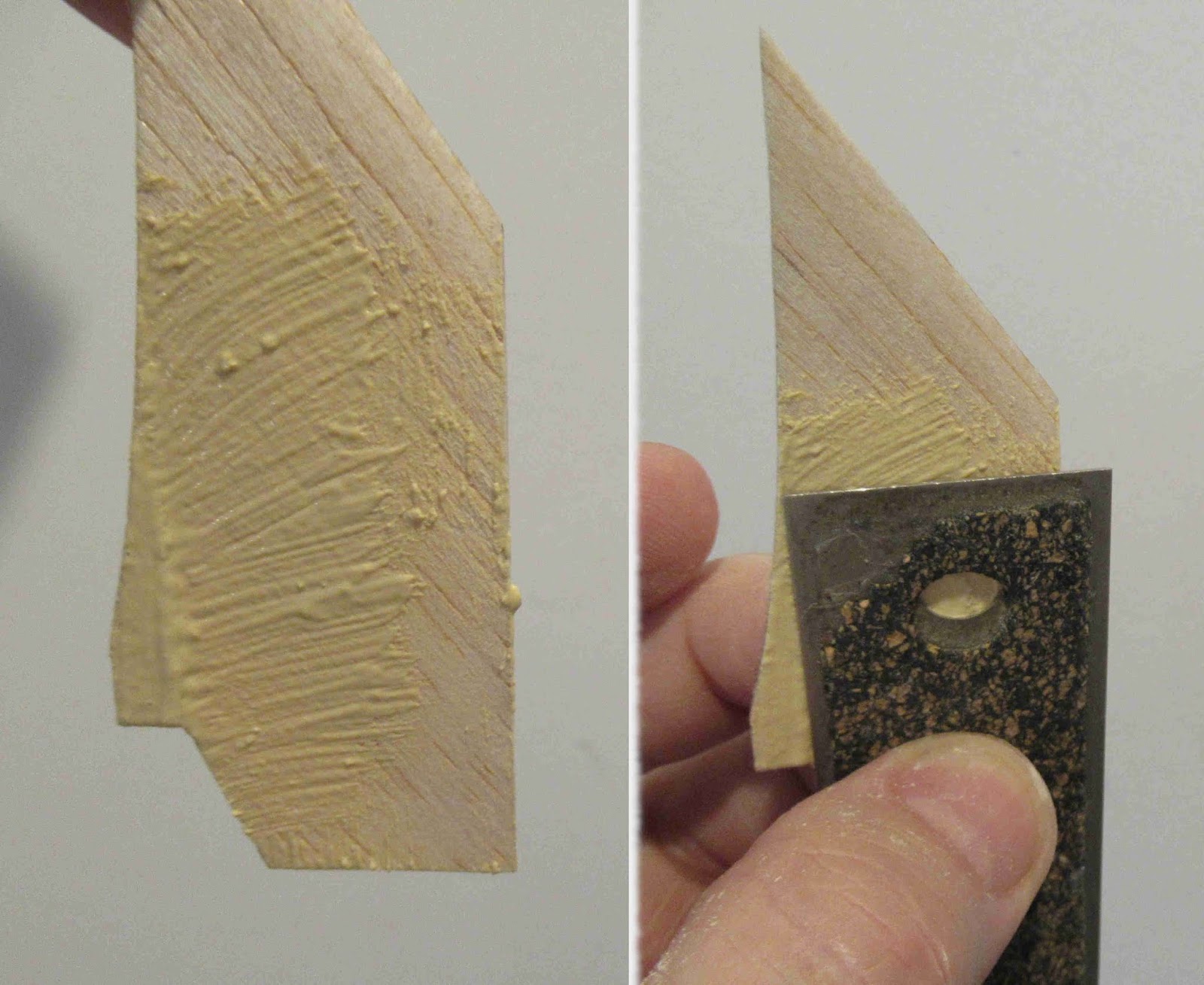
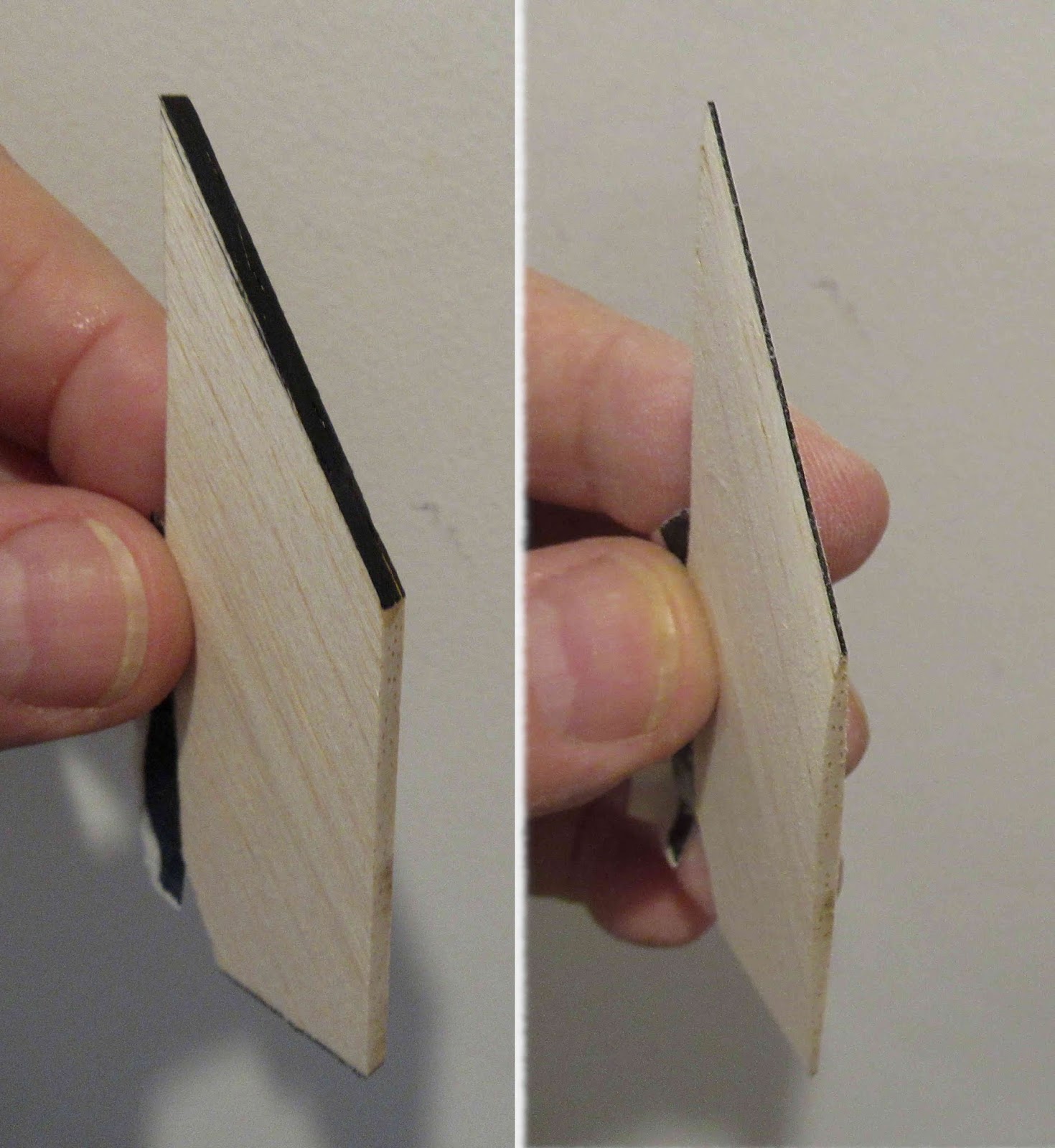
I traced the V2 fin outline, cut it out then cut out a centering square for the 47s. With this piece set into the root edge I could place the eight decals consistently.
Many rocket building techniques have helped with home improvements. I used the same card stock template idea to mark the corners of my cabinets before drilling through the wood doors.
Fin fillet practice makes for even caulking lines around baseboards!
Here's the totallly finished V2 with the small #47s on both sides of all four fins.
Showing posts with label S V2. Show all posts
Wednesday, January 8, 2020
Friday, December 20, 2019
Semroc V2 Build, Finished
The V2 was the first kit I was attracted to looking through that first Estes catalog in 1969. I've built a few larger ones since then.
When this build was started a few years ago, a Kevlar loop was attached to the tail cone. I ended up using a tri-fold mount and some 1/8" wide elastic for a shock cord. A 12" Odd'l Rockets parachute was tied on.
This was a tough mask, made harder because the model is smaller.
Those diagonal strips should have been a little narrower. I'm leaving it as is.
The number "47" decals are yet to be made. The 47s go on the fins in the white horizontal bars.
The finished look is interesting and different from the paint patterns usually seen.
Semroc V2 Build, Part 13, Trim Stripes
I used my favorite black trim material - Contact Paper blackboard covering. It's cheap and a roll will probably last a lifetime.
After the first width is cut, the ends are lifted and stuck back down a little to the right. The others are cut using this as visual guide width.
This White Sands roll pattern is seen on other V2s.
The bottom of the diagonal starts above the leading edge tip of the fin. The upper end is at the midpoint between two fins.
The trickiest part is getting the strips set down in a straight line. Look from the back of the model to make sure the lines are straight, not set on a slight curve.
The long zig-zag pattern is trimmed at the tail cone / tube joint and the bottom of the tube extension.
There are still a decal to be printed, the number "47" that sets on the horizontal white strip on the fins. This will have to wait until I do some kit decal productions.
Thursday, December 19, 2019
Semroc V2 Build, Part 12, Fix!
Why post mistakes, assembly and paint problems? We're all in the same boat, mishaps happen to all of us. Hopefully there are lessons learned that lead to a better build the next time around.
Here's where I was left after pulling the simple around the tube mask. I've seen this before, metallic paints don't stick as well as normal paint. They lift easier and can tear along the mask line.
I didn't want to sand the entire upper extension, then go back to spraying the white and silver again.
I masked off the white to protect it right on the silver mask line with brown masking tape. This is only to protect the white surface while the rough silver edge is smoothed down. I only have to sand the area around the tear. Metallic paint over spraying blends well.
Scotch tape mask went right on the previous line. This was followed by brown tape and copy paper below it.
Whew!
This time I got a clean mask.
Time to glue the extension tube on over the coupler.
Wednesday, December 18, 2019
Semroc V2 Build, Part 11, Extending The Body
I had to make a coupler from a short length of BT-55 to add on the short extension.
1.Cut a segment of tube.
2. Cut vertically down the tube using scissors. Cut in a straight line.
3. Set tightly in tube and trace down the overlap with a sharp pencil.
4. Cut off the overlap with another straight line, just to the side of the pencil line.
You should end up with a tight fit and clean joint seam.
The coupler is glued about 1/3 the way into tube.

On the left is the BT-55 extension slid in place over the coupler.
On the right is the simple mask for the silver paint.
Ah crud! (Not the wording I really used.)
Metallic paints don't always pull clean when masked. This will have to be sanded, masked and painted again.
I thought about setting the V2 aside for a little while.
Did you ever build a model and it seemed cursed? We've all been there. I wasn't happy with the earlier fin mask, it's just okay.
The fix is coming . . .
1.Cut a segment of tube.
2. Cut vertically down the tube using scissors. Cut in a straight line.
3. Set tightly in tube and trace down the overlap with a sharp pencil.
4. Cut off the overlap with another straight line, just to the side of the pencil line.
You should end up with a tight fit and clean joint seam.
The coupler is glued about 1/3 the way into tube.
On the left is the BT-55 extension slid in place over the coupler.
On the right is the simple mask for the silver paint.
Metallic paints don't always pull clean when masked. This will have to be sanded, masked and painted again.
I thought about setting the V2 aside for a little while.
Did you ever build a model and it seemed cursed? We've all been there. I wasn't happy with the earlier fin mask, it's just okay.
The fix is coming . . .
Tuesday, December 17, 2019
Semroc V2 Build, Part 10, Picking The Paint Pattern
The model got a few coats of gloss white, sanding any rough spots between coats. The tail cone assembly isn't glued on yet. Having it separate should make the masking a bit easier.
Now to pick a paint pattern -
There were many different variants from camouflage to the black and white White Sands patterns.
In the Peter Alway book, Scale Bash I found this one named "Blossum". It's different than most, two opposite fins remain white on both sides. A roll pattern with horizontal stripes is on the other two fins.
I didn't read the descriptive copy until I was done painting the black. "The V2 was lengthened by one diameter in the series of eight flights."
Lengthened by one diameter? I'll have to find some scrap BT-55 in the parts drawer.
I didn't take any pictures of the masking - this was not a fun mask.
I used my regular Scotch tape, masking tape over that and a grocery bag for the large areas.
The picture shows the paint lines after touch-ups. The fins bottoms are flat, there is some distortion in the picture.
I used the ACE Hardware Store Premium enamel for the black. This paint dries very quickly so the masking tape has to be pulled almost right after spraying!
Monday, December 16, 2019
Semroc V2 Build, Part 9, Gluing On The Details
The trimmed lug locations were sanded to remove the filler/primer down to the beige CWF filler.
The gluing edges are narrow, more glue was set up and inside the top for an internal fillet. You'll find these much easier to position using long tweezers.
After the glue dried, small fillets were applied with the tip formed Q-tips shown earlier.
The inside ends were cleaned up with a sharp knife.
The launch lug area was sanded down to the body tube and the lug glued in place.
TIP: Check the lug alignment using an aluminum angle set down the tube.
Sunday, December 15, 2019
Semroc V2 Build, Part 8, Launch Lug Trim
The original instructions give a full size template for cutting the turbine exhausts and pull out plugs from standard launch lugs.
TIP: Draw pencil lines extending the cut lines beyond the launch lug sides. Why extend the cut lines? When you set the lug on the full size illustration, the lug covers the angled cut! The extension lines give you something to line up the blade.
Launch lugs are tough to cut, they can be easily crushed. Be sure to use a new, sharp razor blade.
Set the lug over the instruction drawing, line up the blade on the extended pencil lines drawn earlier. It might take some "sawing" back and forth to cut through the lug.
Cut the back end angle first, what's on the right side of the drawing above.
TIP: You'll find it easier to make the first back end cut and sand that edge smooth. Then make the second longer forward angle cut. You wouldn't be able to sand the edges when the small piece is completely cut off the lug.
I actually cut four of each and picked the two that were the closest in size and shape.
Try to get all the sides cleaned up before gluing onto the tail cone. The inset picture shows a clean cut and sanded first cut.
Saturday, December 14, 2019
Semroc V2 Build, Part 7, Gluing On The Fins
Marking templates are cut out and pencil marks made at the fin locations. Set the tail cone and body tube on a table with the flat sides of the templates facing down. After adjustments I taped the marking templates in place and marked the fin locations.
It's not easy to draw a straight line down a curved boat tail.
I set a piece of tape down the two pencil marks and drew a line. Laying a piece of tape down on the boat tail will give you a line that is almost straight, it'll have a very slight curve to it.
The fin was set beside the line to gauge the position height. The primer/filler was sanded down to the CWF for a stronger bond.
The instructions say to build up fillet layers that taper and get wider to the rear. The older instructions say to do three layers of glue, I did four. They did look thick when drying, but after paint they didn't seem wide enough.
This illustration shows some very wide fillets!
Friday, December 13, 2019
Semroc V2 Build, Part 6, Gluing On Servos
The servo slot is cut out of the fin template.
Set this over the fin and do a pencil tracing inside the servo slot.
The right side shows the servo glued in place. I'm checking the position with the template.
Servos are glued on both sides of the four fins.
Look over the trailing edge and from the side to line up the opposite servos.
I wanted to apply glue fillets around the servo sides but keep them small.
On the left is a Q-tip right out of the box. The head is pretty wide.
TIP: On the right I've spun the cotton between my thumb and index finger, forming it into a narrower tip. This will keep the fillets small.
Apply a thin line of glue on the servo edge. Remove the excess and smooth the glue with the tapered Q-tip.
On the right is the finished fin ready to be glued onto the boat tail.
Thursday, December 12, 2019
Semroc V2 Build, Part 5, CWF Balsa Fill
The nose cone and tail cone shoulders weren't sharp.
Here I've brushed some CWf over the shoulder edge. While it is wet, it is quickly pushed into the body tube and turned. Let this dry and then sand even with the sides of the tube.
You'll end up with a much sharper shoulder corner.
I was concerned about keeping the fin line sharp.
TIP: CWF was brushed on. While still wet, the edge of my straightedge was pressed into the filler and the ruler drawn down. This give you a straight line with less chance of sanding away the edge.
Here's the "molded" CWF after being pressed into the recess.
You have very little to sand off near the line and only have to level the raised filler at the top.
The fins and servos were taped down and sprayed with filler/primer.
Notice the tape strips rolled up onto the root edges to keep the filler/primer off.
On the right - the filler/primer has been sanded off the fins and servos.
Wednesday, December 11, 2019
Semroc V2 Build, Part 4, Fin Shaping and Servos
A flat diamond file was used to do a final squaring up to the sand line.
After all four fins were shaped, the remaining
black ink is sanded off.
The X-Kit supplies the narrow fin servos laser cut on the balsa fin sheet. These are small and would be difficult to fill.
When this model was initially worked on, I cut some servos out of basswood. Look close - At that time I laminated some 1/16" basswood to get them to the correct height.
More before and after pictures:
On the left is the squared servo profile.
In the middle the ends have been rounded.
On the right the top and taper to the rear have been rounded.
Tuesday, December 10, 2019
Semroc V2 Build, Part 3, Fin Shaping
Here's the larger semi-scale fin.
If I were to use the smaller scale size fin, Semroc recommends an additional 1/2 oz. of nose weight along with the washer weight held in place by the screw eye. That seems like a lot of extra weight. I'll go the easier way out and use the wider fins.
Notice the pencil line at the root edge. This area to the left of the line remains square, the airfoil is to the right of the line.
The edge of the masking tape was blackened with a wide marker.
The strip was set on the pencil line, protecting the area to remain square.
Here the fin is held upside down.
The tape is used as a guideline for the edge of the sanding block. Be careful, you can sand off the tape.
Here's before and after pictures.
I did my standard wipe of medium CA glue down the leading (upper) and trailing (lower) edges.
A wide Sharpie marker is used over the area with the dried CA glue. The glue prevents the marker from being absorbed into the wood. The ink gives you a very high contrast making it easier to see the width of the sanded airfoil edges.
Monday, December 9, 2019
Semroc V2 Build, Part 2, More Parts
On the left is one of the "scale" sized fins I had cut and shaped earlier. These smaller fins require an additional 1/2 oz of nose weight in addition to the washer weight at the nose cone! I'll be making the larger fins.
Two of the three launch lugs are cut to make "pull-out" plugs that glue to the tail cone between the fins.
The gauze square is used to hold the shock cord inside the body tube. I don't remember any other kit that used this gauze for shock cord retention.
Along the bottom are the small fin actuators. The kit does supply them laser cut from balsa but I shaped them from basswood. It's not any fun to try and fill balsa grain on small parts like this. I'll only need eight of them. I cut out a few extras.
Here's the Estes fin templates - the larger semi-scale and smaller scale fins.
These templates will be used later to consistently position the actuators.

I had previously tied some Kelvar to the engine block before gluing the engine tube in the tail cone.
Look close at the sides of the tube - they are out of round!
I have no problem sliding an engine in and out from the bottom. The top of the drilled tail cone is a little off. This won't effect the flight of the model.
Two of the three launch lugs are cut to make "pull-out" plugs that glue to the tail cone between the fins.
The gauze square is used to hold the shock cord inside the body tube. I don't remember any other kit that used this gauze for shock cord retention.
Along the bottom are the small fin actuators. The kit does supply them laser cut from balsa but I shaped them from basswood. It's not any fun to try and fill balsa grain on small parts like this. I'll only need eight of them. I cut out a few extras.
Here's the Estes fin templates - the larger semi-scale and smaller scale fins.
These templates will be used later to consistently position the actuators.
I had previously tied some Kelvar to the engine block before gluing the engine tube in the tail cone.
Look close at the sides of the tube - they are out of round!
I have no problem sliding an engine in and out from the bottom. The top of the drilled tail cone is a little off. This won't effect the flight of the model.
Friday, December 6, 2019
Semroc V2 Build, Part 1, Parts
The Semroc V2 is a clone of the old BT-55 Based Estes V2 kit. It looks like the Semroc V2 kit has been discontinued. ASP now offers a BT-55 V2 kit along with 13mm and 24mm engine kits.
I first saw the Estes V2 in a "temporary" Estes catalog around 1969.
TRIVIA: Estes had run out of their standard sized catalogs and produced something to get them through a very busy sales period. The catalog was made up of black and white prints, four reduced kit descriptions per page.
I was immediately attracted to the V2 and ordered the kit a short time later. I noticed how much stronger the BT-55 tube was compared to other BT-20 models I had seen up close.
This version was from the Semroc X-Series. A full color face card and parts list is included in the Semroc kit. The instructions are to be downloaded from online sources like Jim Z's. To see the Estes V2 instructions, CLICK HERE
I had started this kit and for some reason set it aside. The engine mount is glued in the tail cone with a Kevlar leader. The smaller "scale" fins were cut out and shaped. The washer weight and screw eye are glued into the nose cone. The parachute is missing. We'll take it farther forward from here -
Subscribe to:
Posts (Atom)