Showing posts with label Coupler. Show all posts

Sunday, April 20, 2025

D.I.Y. Couplers - Tip


I needed a coupler "sleeve" to fit a Centuri sized ST-18 (1.8" diameter) tube.
This is for a second prototype of a possible Odd'l Rockets ROBOT kit.

You can't find couplers in this size so I'll have to make one using a 1" length of the ST-18 tubing


Cut the coupler in a straight line using scissors.

Slip the cut coupler and mark the overlap with pencil.
On the left, you can see the pencil line.
Cut off the overlap, not directly on the line, but a little large.

Test the fit in the outside tube. 
Is it is too tight, you can sand to fit with some 220 grit on a block. 
Enlarge the right side picture to see a perfect fit in the tube.


Thursday, January 2, 2025

Estes Black Star Voyager Build, Part 3, Engine Mount


Here's the finished mount with the notched centering ring glued up against the black retainer ring. The flat face of the ring is spaced 1/2" from the rear of the engine tube.


Again, I used my aluminum angle to glue on the upper (Part L) tube in line with the engine mount.
Jumping ahead:
The base of the adapter has holes cut to allow the ejection charge gases to pass through and deploy the parachute. I don't remember ever seeing ejection holes made through a plastic adapter.

Pencil mark the hole positions before drilling. The four holes should be around 1/8" diameter.

Wednesday, January 1, 2025

Estes Black Star Voyager Build, Part 2, Engine Mount


The shorter engine mount tube (Part A) is joined to the longer Part L tube. 

The low 1/2" of the Part A tube is exposed, covered by small cardstock vanes. I went ahead and filled the tube seam with CWF, then filler/primer and sanding.
The green coupler doubles as an engine block, butting up against the upper bend of the engine hook.
The fit was loose, I built up the diameter with some rings of wood glue.

The slit for the upper bend of the engine hook is cut at 3 3/32" from the bottom.

I used my aluminum angle to insure that the two tubes were in line as the glue on the green coupler set up.


The instructions say to mark the low tube 1/2" from the bottom.
The illustrations show 1/2" space from the centering ring to the low end of the tube.

The pencil line is 1/2" from the bottom of the tube.
I set the black retainer ring a little above the 1/2" line so the face of the notched centering ring will end up at the 1/2" mark. (See next post)

Tuesday, December 17, 2024

Estes Constellation Build Part 11, Odds & Ends


This lug standoff probably isn't needed, the payload section isn't wider than the low end tube.

This style of standoff goes back to when Estes sold it's "C Rail". The dowel standoff fits the C Rail launch rod.

TIP: A BT-50 tube reinforcement coupler was made out of a split piece of body tube. This was glued in place in the tail end, pushed in place with the engine mount.

I'm tired of BT-20 and BT-50 models crimping and buckling right above the fins. That's a weak point when the model touches down.

This coupler should strengthen that weak area that's prone to bending.
After the strengthening coupler was pushed into place the engine mount was quickly removed.


Another line of glue was applied with a dowel end and the mount slid into place. The rear centering ring is even with the back end of the main air frame tube.

To be sure the ring is flush, the last 1/2" was pressed in place with the flat side of my sanding block.


The rear ring was "sealed" with some medium thickness CA applied with a Q-tip.
This hardens the outside surface and can be smooth sanded with 400 grit.

Monday, September 30, 2024

Enerjet by Aerotech, Arreauxbee-Hi, Part 9, Engine Mount, Launch Lug & Screw Eye Fitting


With the lower body tube turned over - 

Here's how the engine mount sits, recessed into the body tube.
Note the centering ring is right at and even with top of the fin slot.

With the fin locks in line with the fin slots, test the position by sliding a fin or two in place. You don't have to snap the fin tabs in place yet, just be sure the fins project straight out.


It could be difficult to apply CA glue to the rear fin tab/fin lock joint.
TIP: As shown in the last build, set a toothpick tip into the joint. Drip the CA glue onto the toothpick, enough glue so the drop runs down the toothpick and into the joint.   
The paint was scraped off around the launch lug slot.
Notice the low end of the raised alignment tab stops at the bottom of the lug. 
DON'T SCRAPE the the paint past the bottom end of the slot. The raised lug base sits down to the bottom of the slot.

The picture to the right shows how the CA glue was applied. The glue is applied towards the center so it won't squeeze out beyond the edges of the lug base.


The screw eye is turned into the coupler bulkhead.

TIP: On the right, notice the screw eye isn't screwed in beyond the threads. If turned in past the threads, the screw eye will be loose. The threads help lock it in place. Apply glue on both sides of the screw eye.

Saturday, August 31, 2024

Enerjet by Aerotech, Astrobee D Build, Part 22, Coupler Gluing

Here's the directions to glue in the tube coupler.

While the model is constructed using medium CA glue - 
I'd recommend using epoxy for gluing in the coupler.

If you don't have experience using two-part Epoxy glue:
1. Wear gloves, you might be allergic or over time develop a epoxy skin reaction.
2. Parts (like couplers) glued using epoxy can slide before it sets up. Slide the coupler in up to the 3" pencil mark, but check back every few minutes while it dries. If drying vertically, the coupler/tube assembly could slide and lock up in the wrong position.

I used a rolled up grocery bag to keep the shock cord inside and out of the way.

Epoxy was mixed and applied inside the upper tube so any excess would stay inside and not be squeezed out onto the coupler.

The coupler is slid in and turned while sliding it up to the 3" pencil line. 
Turning the coupler spreads the glue evenly and makes a smooth fillet bead at the top inside edge of the coupler.

Thursday, August 1, 2024

Enerjet by Aerotech, Astrobee D Build, Part 5, Engine Mount & Upper Tube Bulkhead

Gotta' love instructions when they get things right!
Something I've been harping about for years -
1. Use a Square Knot to tie a shock cord to the screw eye. A "Granny knot" can slip!
2. Do not put cement on a knot! Cement (glues) will weaken the shock cord.


The ejection baffle is glued into the top end of the tube. In the last post the 1/4" slits were cut in the top of the tube.

The second centering ring is glued onto the top of the ejection baffle.

The screw eye is screwed into the hole in the top of the ejection baffle.

The shock cord is tied to the screw eye with a square knot.


Jumping ahead to the Upper Body Prep and Assembly:

The screw eye is turned into the bulkhead plate.
Be sure not to screw in too far. Leave a bit of the threads still visible. If you screw in too far, the screw eye won't hold.


Tie on the second shock cord with a square knot.

The plate is glued onto the coupler with the screw eye facing down.


I applied a wood glue fillet on the inside joint using a Q-tip taped to a dowel.

Tuesday, September 6, 2022

ASP Micro Sandia Sandhawk Build, Part 5, Nose Cone & Coupler


There are some small nubs in the shoulder base left from the 3D print process. Sand them off with a block.

The nose cone is glued into the shorter upper tube with Fabri-Tac.


The longer coupler gets a small hole "drilled" into the top.
After spinning a blade tip, the hole was rounded out using the tapered end of a mechanical pencil.

The inset picture shows the Kevlar line tied through the hole. 


The coupler is glued all the way into the upper tube. The upper end of the coupler butts up against the shoulder of the nose cone.

The coupler that sticks out the back is the shoulder that joins the two tubes.


The nose cone joint seam got a CWF fill.


After sanding down the CWF, the body got a shot of filler/primer and sanding.

Tuesday, April 5, 2022

Estes EAC Firecat #0821, Build, Part 3, Closing The BT-48 Tube Joint


You'll need an interior patch to hold the butted joint seam on the BT-48 tube.
Cut a piece of cardstock about 1/2" wide and 1/4" longer than your body tube.

Pre-curve the piece in your palm using a rolling dowel until you get an arc as shown in the inset picture.
I used a thin coat of wood glue spread evenly over the entire piece.

Press in place centered over the joint. Use the dowel to apply pressure over the patch piece.

After it dries, sand the overhang off using a sanding block until the patch is even with the ends of the body tube.

When you are stuck without a proper part - 
Using this method, you can make couplers to join segments of body tubes.

To smooth out the joint,
Apply a small line of glue the last 3/8" on both sides. 
Wipe off the excess with a fingertip then immediately burnish and roll over the seam with a smooth pen barrel. Pressing the loose fibers into the glue should smooth out the cut. 
The ends will be exposed on the finished model.

Monday, April 4, 2022

Estes EAC Firecat #0821, Build, Part 2, Fitting The BT-48 Tube

You could simply use a standard BT-50 or a yellow spacer tube for the low intake/motor tube and nobody would notice the difference. But what fun it that? 
Tube cutting experience should be part of your rocketry skill set. The diameter of the 2 1/2" long BT-50 tube will have to be smaller to slide into a standard BT-50, like a coupler.
 

Use your aluminum angle to draw a straight pencil line down the length of the tube.
You can use the angle as a guide to cut the first line.

Slide the slit tube into the longer BT-50 and note the overlap. The overlap will have to be cut off.


Slide the slit tube halfway into the main BT-50 tube.
Trace down the overlap halfway down. Flip over the tube and trace the other side.

You might end up with angled lines. It's difficult to get a straight line because the tube shifts.

I prefer to cut the second line with scissors. It's better to cut inside the pencil line a little wide at first.

I used my sanding block to clean up the line to fit into the BT-50.


Here's a good fit of the new "BT-48" tube slide into the main BT-50H. 
The segment joint is clean and the slit tube slides easily into the BT-50H.

Tuesday, December 14, 2021

Estes Skylab #001973, Build, Part 2, That Darn Reinforcement Ring!

GOTCHA: It seems like the internal reinforcement ring has always been a problem.

Too many first timers (I was a once first timer) assume that it will just slide in after glue is applied.
You will have to cut out a small segment to get a slip fit.

Be sure you have the correct reinforcing ring, it is the 1" length of tube.

Try a dry fit or the ring - it won't easily slide in.
Don't try to force it!

The picture on the right shows the rough edge of the body tube. The larger the body tube, the harder they are to cut clean. Square up the tube edges with sandpaper on a block. 

Cut one straight line through the ring using scissors.

Set the ring in the tube and check the overlap. This is how much will need to be removed for a good fit.

It's best to cut the segment a bit short and sand to fit.


Sand and square up the ends. Check the fit.
Repeat - 
Repeat - 
Repeat - 
Until you get a good fit.

Wednesday, July 7, 2021

Estes Space Twister #7258, Part 7, Strange Reinforcement & Green Mask

I mentioned earlier, the BT-50 body tube seemed weak. 
There were two seams to fill, one was the typical glassine seam. The second one was underneath, where the clear glassine shrunk into a slight separation of the brown wrap underneath.  
The tube was already showing crimps from handling when building the rocket. I've never seen a tube this bad since the MRC Enforcer build: CLICK HERE  

I did something I've never done before.
There are flyers that like to "bulletproof" their models by using a long coupler all the way inside the body down to the engine mount.
I know this tube would crimp above the engine mount after the first flight.

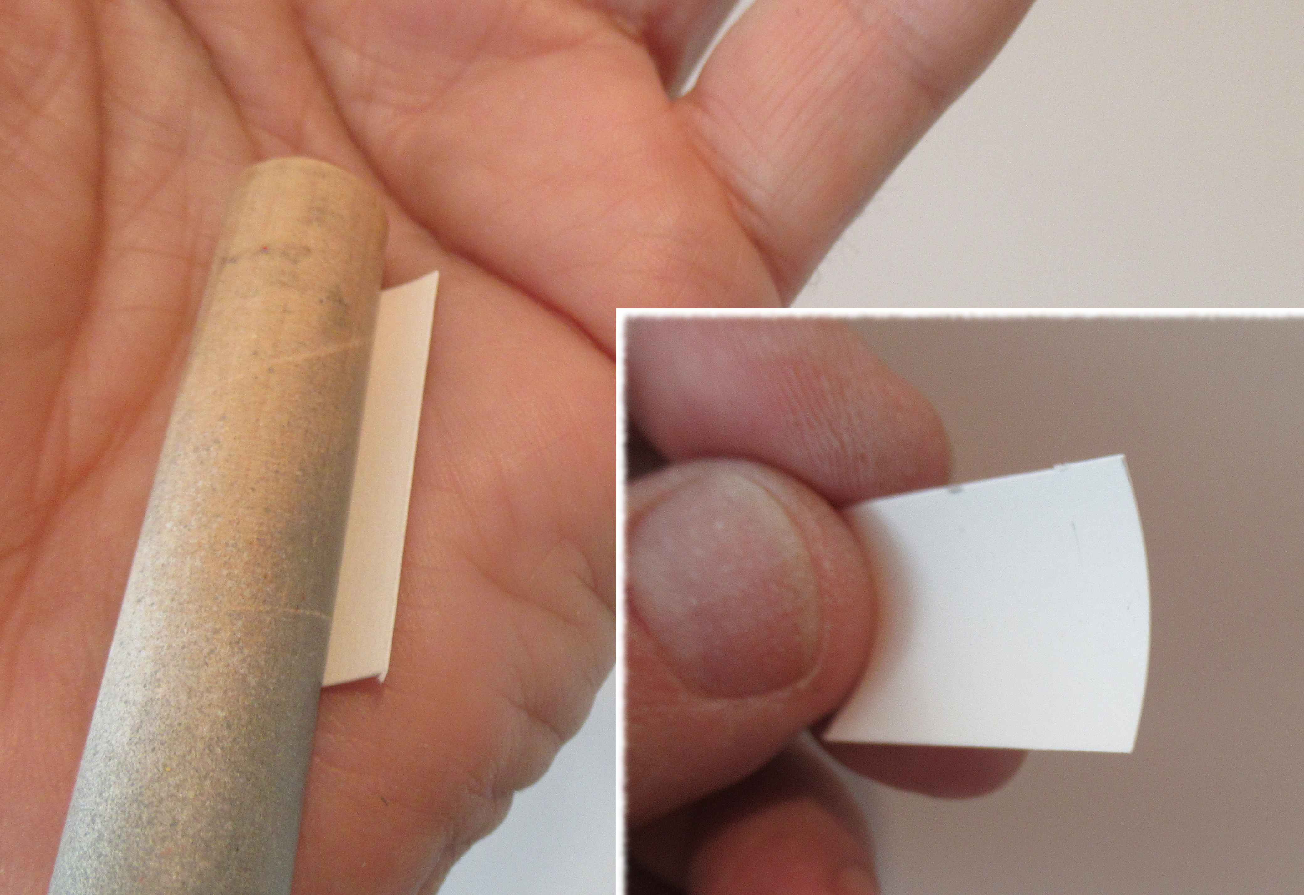
I have some long BT-50 couplers ordered from BMS. I slid the long coupler in, all the way down until it touched the upper centering ring of the engine mount. The top was marked, then the top was cut back to clear the nose cone shoulder. The upper picture shows the shoulder allowance marked before cutting the coupler to length.
 
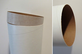
The coupler was slid in without using any glue. I probably wouldn't have gotten the whole length in if glue were used.
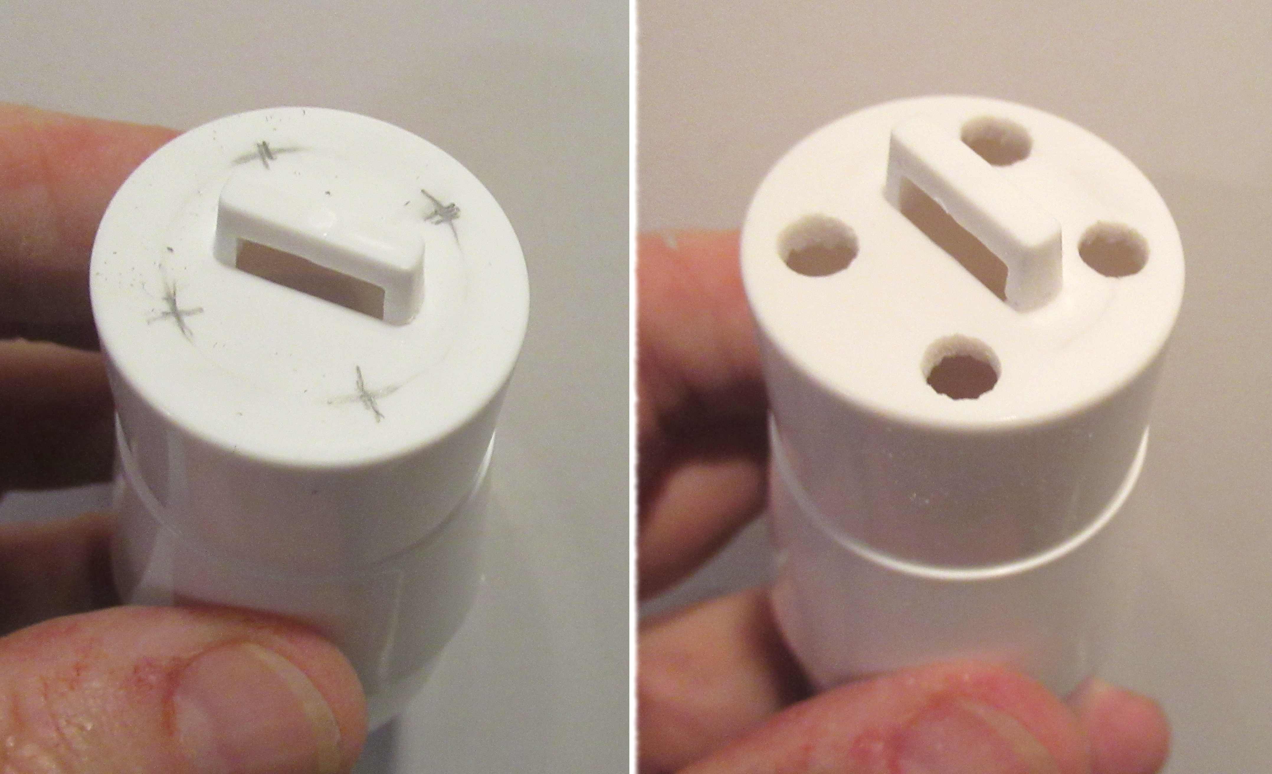
The picture shows the coupler inside, you can see the the coupler recess for the nose cone shoulder fit.

This length of coupler added 1/2 oz. weight to the model! I wouldn't recommend doing this unless you couldn't see any other method to strengthen the tube. This is not a high performance rocket, the spinning boost will definitely hurt the altitude. The added heavy coupler doesn't help.


This wasn't an easy mask. The green color is on one side of the fins, and under the spin tab. 

The tape had to be cut thin and tucked into the crux under the top of the spin tab.
The lower picture shows the masking tape over the larger areas.
Green paint coming up - uh oh!

Thursday, February 25, 2021

ASP MMX Jayhawk Build, Part 2, Parts Prep


Before sliding the couplers into the tubes -

Round off the edges with some 400 grit sandpaper.
The rounded coupler won't fold in the edge of the body tubes.


On the left is the tube ends butted against each other. Small tubes are difficult to cut square.
Square up the tubes with 400 grit on a sanding block.

On the right are the same tubes after sanding and truing them up.
The marking guide matches up and fits the little tube diameter!
Thanks A.S.P.!

Here's the kit supplied small plastic angle to mark the body tubes for the fin locations.

Hang onto the marking angle - you might need it for a future MMX build.


The base and shoulder of the nose cone needed a little squaring up.
Not a big deal - the outside surface was smooth and the slot cut very clean.

Saturday, January 9, 2021

Semroc Laser X, KV-33 Build, Part 2, Adapter Assemblies


You make two adapter assemblies, one for the engine mount, the other for the mid body adapter.

The centering ring with the two holes is used in the upper adapter. A Kevlar loop is tied through the two holes. Some Centuri kits used a shroud line to tie the model together instead of a screw eye in a balsa adapter.


TIP: The coupler ends can be sanded for a flatter gluing edge.

Tubes and coupler ends are usually cut at a slight angle. 


The centering rings are glued onto the coupler ends.
Lay the glue bead with a bit more on the inside edge. Set the ring on and twist it, making a more even inside fillet. 


You can smooth the interior fillet and remove excess glue using a Q-tip. 


The Kevlar in this kit was braided. To prevent fraying you can rub some white or wood glue on the ends. 
TIPS: Never use CA (super glues) on string, cords or knots. CA glue will make the line hard, brittle and easy to break.
The instruction illustration shows a bigger loop than is necessary.