Saturday, March 31, 2012

Ranger Clone Build Part 4 Engine Mount

These engine mount tubes are thin BT-20 based and the outside surfaces a little rougher than I would have liked.
A layer of 24 lb. copy paper was glued around the tubes. This is strictly structural and added a lot of strength to the low ends of the tubes.

Looking back, it would have been easier to do this before the engine hooks were glued in place!


All three tubes were dry fitted (no glue!) side by side in the longer BT-60 tube.

The tubes were turned until all three engine hooks were in the "open side area" position. You want to be able to raise the engine hooks so they easily clear the inside of the BT-60 tube.

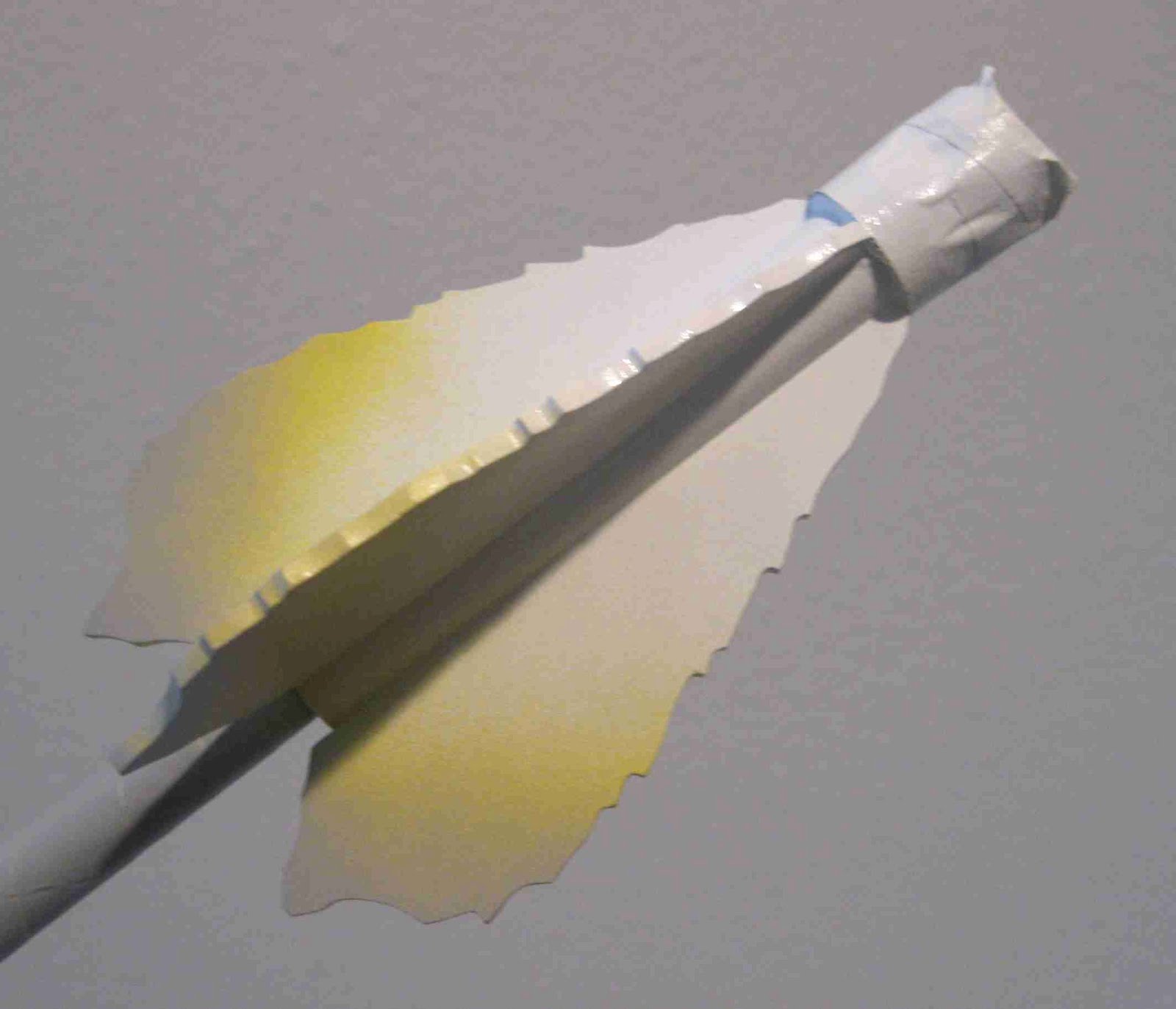
From the rear, the tubes were pencil marked where they touched. These marks will be the glue lines.


Extend those pencil marks you just made down the length of each engine mount tube.
Each tube will have two gluing lines.

Ranger Clone Build Part 3 Engine Mount


Once the cardstock and engine hook are straight, burnish down the glued card strip with a clean dowel.


The supplied engine blocks were a little short at 3/16" long. I notched the engine tubes at 1/4" before checking. Not a big deal, they won't be seen once glued inside the model.

With the upper end of the engine hook below the engine block ring, It could go in crocked. You should glue the engine block in straight, not at an angle.


I used an engine casing to press the engine block in. This way the emgine block won't be set in at an angle.


After I was sure of a straight fit, a fillet was applied to the top of the tube / block joint.

Friday, March 30, 2012

Ranger Clone Build Part 2 Engine Mount

The original Ranger had the cluster tubes glued side by side.

I wanted to add engine hooks instead of simply friction fitting with masking tape.
Any type of engine hook retention might get in the way when all three engine tubes are glued together. Three wraps of tape or mylar rings would make the tube assembly wider than the inside diameter of the BT-60 mainframe tube.

In the picture a 1/8" slit was made 1/4" from the forward end of each tube.
The engine hook is set in the slit.

The picture above shows a rectangle cut from 110 lb. cardstock - 1/2" wide x 1 5/8" long. This will be glued over the engine hook to hold it in place.

A coat of white glue is applied to one side of the cardstock piece.
Set it on the hook and center it from the rear before burnishing it into place.
Be sure the engine hook is straight down the tube.

HPR Design Post on TRF

Sean A. (GrossApproximator on TRF) really summed up my feelings about many HPR designs:

"All the high power rockets I see look very similar to one another. Nose cone; tube; fins. Some are big, some are small, and some are honkin' huge. Some have simple paint jobs while others have more complex paint jobs. However, other than the honkin' huge rockets, I've never seen a high power rocket that I really liked the look of. Since rockets spend 99.99% of their lives on the ground, I want to see a rocket that looks so wild that you can't take your eyes off of it--even if the rocket only ever flies once or twice."

Sean is right, many HPR rockets have a predictable design profile.
This is nothing against HPR models.
A well planned, successful HPR launch is amazing to see in person.

Sometimes I wish I had the money, time and tools to make larger rockets!

Thursday, March 29, 2012

Ranger Clone Build Part 1 Parts


On the left is how the Ranger looked in the 1968 Estes Catalog.
Inset on the right is the Ranger shown in the 1971 catalog. This build will have the 1971 paint scheme.


Here's the parts for the build:
Originally I wanted to build the Ranger from a Baby Bertha kit. The fins are very close. But, I did cut 1/8" thick fins from the Ranger plans from JimZs - HERE
The Baby Bertha body tube is 7 1/2" long. Cut that down to 7" and you would only have to add a 11" length of BT-60 for the lower tube.
That and some BT-20 for the three engine cluster tubes, a 60 sized balsa nose block and you are good to go!

I'm upgrading a few things from the original Ranger parts.
The 3X 18mm engine mount assembly is from jonrocket.com. This build will add three engine hooks. Friction fitting a three engine cluster into thin BT-20 tubes could be a problem. A modified plywood 50/60 centering ring is added to the top of the engine mount to prevent the ejection charge from exiting out the back. While the picture shows a plywood ring with three holes, I'll show how to make a ejection blocking ring from a more common single hole plywood 50/60 centering ring.

In the parts picture there is what looks like a baffle plate. I'll be ordering the equivalent Semroc part, #EBR-60W.
This single punched disk keeps the parachutes higher up in the lower mainframe tube during boost. It also adds a elastic shock cord connection point. It is not a full baffle assembly and wadding is still required.

Newer Estes parachutes will be used, they have a good vintage look to them.

New Estes Parachute Shroud Lines

I was checking the shroud line attachment knots on two of the new Estes 12" parachutes.
On one parachute, two of the six loops were a little big.
I was going to re-tie the knots so all six were more consistent in size.

While using my tweezers to gently take the knot apart, the line broke!
Checking the other knots I noticed two were tied with "granny" knots and not square knots. Square knots don't slip when pulled, granny knots can slip and come untied.

I decided to re-tie new shroud lines on the two parachutes.

Out of curiosity, I tried to break one of the shroud lines that was removed from the parachute.

It broke very easily, almost too easily. The thinnest sewing thread you could find would be stronger than the shroud lines attached to the pre-made Estes parachute!
While I really like the retro printing on the new, cheaper Estes parachutes, I replaced all the shroud lines.

I'm not saying all the new parachutes have this shroud line material. There is no way to know, I may have gotten a bad lot. Both parachutes I purchased had the weak lines.

Wednesday, March 28, 2012

Dr. Zooch SLS Finished


As far as I could tell, three NASA meatball logos are place 120 degrees from each other. You can see the small, vertical UNITED STATES decal set on either side of the upper core tube.
The kit provide you with a United States flag printed on cardstock. I found a flag online and added it to the decal sheet. My flag decal width is a little less than the cardstock flag provided.

This is really a great looking model when seen in person. I especially like the Saturn V decor. It's good to have the option of different finishes.

Lessons learned:
1. I usually read ahead and should have avoided gluing the launch lugs in the way of the support struts. It's a compromise I guess, the launch lugs aren't so obvious but the struts on the lug side are small.
2. If you want to use the supplied Saturn V wraps, you'll have to plan ahead and make adjustments to the order of construction.
3. I followed the Space.com artistic rendering for placement of the SRBs on the core body. On my model, the SRBs don't overhang the rear body as much as they probably should. I'm taking a chance here, but a model this length with six trailing fins should be stable.

The instructions recommend a B6-4, C6-3 and C6-5 engine. NO A ENGINES!

Tampa TTRA Launch Pictures, March 17, 2012


Roger Smith (JonRocket.com and RocketReviews.com) took some great pictures at the last Tampa TTRA launch.
While this blog concentrates on LPR rocketry, Roger took many more pictures of Low, Mid and High power launches HERE

The first launch of my SUPER ALPHA with a C11-5.


Drag race of Lonnie Buchanon's ANGRY BIRD and my PIGASUS.


The first flight of the Dr. Zooch SLS with a C6-5.


Mike Nipper's EASTER EGG.

Tuesday, March 27, 2012

Dr. Zooch Flame Fins Part 5


Three flame fins glue on each SRB fin tube assembly.

They are spaced at 90 degrees to each other. It's almost like a four finned rocket with one fin missing. The open area of the tube faces the central engine mount.

Mask off the small centering rings and spray the fin unit white.


On the left is the sprayed and blended yellow paint.
If you were holding the fin unit at this angle, you would be aiming the yellow spray nozzle just below the bottom border edge of the picture.
Start pressing the spray nozzle at the left before the fin edge. Spray in a straight line.
Continue across the lower fin edge and release the nozzle when you are past the fin on the right.
Spray light mist coats until you reach the color density you want.

On the right is the third color, the gray primer.
Spray as you did before, but aim lower than you did with the yellow.
Try for an even blend.
When you do a blended finish, your finish will be dull at the color change area.


Here's all three variations from different builds.
I prefer the third with the white, yellow and gray coloring.

Dr. Zooch Flame Fins Part 4


Here's an image of a Shuttle launch.

Notice the color changes in the flame.
It goes from a very bright white, to yellow (maybe a slight orange also) to grey smoke.


I've made a few sets of Zooch Flame Fins before.

A first attempt at the left looks almost "cartoonish".
I had the right idea but the rear orange color was a little much.

On the right are the fins from the Zooch Thor Agena.
The white to yellow is better, but it needs the gray color.

Monday, March 26, 2012

What? No Posts on March 25?

Sorry about that!
I was in transit between the cruise ship and home.
I'll be home for a while and posting on a daily basis.

Dr. Zooch Flame Fins Part 3

The fins got a coat of thinned CWF and were sanded with 400 grit on a block.
The angled and round side of the block were used to sand the concave lines of the leading and trailing edges.

A second coat of CWF was applied on the leading and trailing edges. I was trying to square up and made the edges sharper.

I wouldn't recommend trying to round the edges on flame fins. It would weaken the sharp edges and be near to impossible to fill all the nooks.


Here's all six flame fins stuck down on their root edges for a shot of primer.

Dr. Zooch Flame Fins Part 2


The sharp angle bend over the edge of the block was used to sand the tight inside corners.

These don't have to be as sharp as the fin pattern shows.
All six fins don't have to have the same profile.


After sanding two fin sides together, the pins are removed.
Don't worry, the CWF will easily fill the pin holes.


The fin on the left is the simple block cut, pinned and ready for sanding.

The fins on the right show the edges after using the different curve and sharp angles of the sanding block.

Saturday, March 24, 2012

Dr. Zooch Flame Fins Part 1

I don't try to cut all the sharp edges of the flame fin pattern.

I use a straightedge and cut straight lines just at the points of the outside edges.
I don't usually use a pen to trace around a fin pattern. Ink can show or "bleed" through a final paint color.
I used a pen to illustrate how I cut out the fins.


There are six fins in total.
Two at a time are pinned together for shaping. Before pinning, I square up the root edges. The front and rear of the fins should be "close" to flush.


The wider concave "dips" were sanded with the rounded side of my wooden sanding block.

Dr. Zooch SLS Build Part 31 Engine Bells & Decals


Instead of the recommended Testor's #1180 Steel I used Testor's #1145 Gunmetal Steel. It's not quite a full black and looked great on the nozzles.
For painting, the nozzles were stuck down to some masking tape, sticky side up. The small end of the nozzle was set on the tape. This kept the paint off the small end gluing edges.

The engine bells were tacked in place with white glue.
Center the bells evenly inside the fairings.

After the white glue set up, I went back in with some medium CA applied with a toothpick. I made sure I got a CA fillet along the inside edges of the bell.

The yellow trash bag parachute was assembled.
To make a tri-fold shock cord mount, the instructions say to: "cut a rectangular strip that is 1/2" wide and just over 1" long."
I've seen this in the Dr. Zooch instructions before. Considering the elastic shock cord is 1/4" wide, this piece of cardstock seems very small.
I cut my tri-fold piece from left over kit cardstock, it measured 1" wide by 2 1/2" long.

Looking back on the latest Space.com artistic rendering, the words UNITED STATES and a NASA "meatball" logo were added.
Up to this point, the upper section of the SLS is all white. I wanted to add the additional decals to make it more interesting.

Here's the decal sheet I made up.
I hate to waste most of a decal sheet for such a small set of decals, so I added a vertical "USA" and many upsizes of the SLS decals I needed. It's a full 8 1/2" X 11" decal sheet with plenty of NASA logos, Flags, USA and UNITED STATES decals for future use.

Patreon members: If you'd like a PDF of this art to make your own decals, email me at oddlrocket@bellsouth.net and ask for the NASA/USA decals PDF.

Friday, March 23, 2012

Dr. Zooch SLS Build Part 30 Feeder Line & Engine Bells

If using the Saturn V wraps, you have to wait to glue on the feeder line.
The shaped feeder line dowel was sealed and sanded with two coats of varnish.
It was painted before gluing on the core body.

Instead of cutting away the cardstock wrap to fit the ends of the feeder line dowel, I made recessed notches in the dowel to overlap the cardstock wraps.

Look close in the picture and you can see where the paint was scraped away for a better bond of the white glue. Be careful if you scrape away paint like this, sometimes the paint will want to chip. Keep the scraped line narrow until you see how the paint comes off. Then widen the line but keep it narrower than the width of the feeder tube.


Four engine bells are formed.
Here I'm sanding down the smaller end so the gluing edge is flat all the way around.


The edges will roll over a little bit from the sanding. Don't remove this rolled edge. The wider edge gives a bit more gluing surface.

Thursday, March 22, 2012

Dr. Zooch SLS Build Part 29 SRB Struts Oops!

My placement of the launch lugs was wrong!
I didn't want them down the middle of the core tube and thought a side placement wouldn't make them so obvious. I glued them to the side allowing for the launch rod clearance between the SRB skirts and engine fairings.

I didn't read ahead seeing the placement of the SRB struts.
The struts next to the lugs ended up being very small!
Read ahead and plan better than I did!


This is the back (end up until now) with the struts in place.
The flame fins are in place but not pushed all the way in.

Dr. Zooch SLS Build Part 28 SRB Struts

You will need the add the SRB struts for strength. These keep the SRBs on the core body when you slide in or pull out the flame fin assemblies.

I sealed and painted the dowel white before cutting into eight 1/2" long pieces.
The angle was sanded onto both ends of the dowel.

For a better seam and glue joint, a slight curve was added with a half round diamond file. This will better follow the curvature of the adjoining body tubes.


The ends of the struts got a drop of glue and they were set in place with long tweezers.


Any excess glue was picked up with a Q-tip.
TIP: Q-Tips are great for getting glue out of tight areas where your fingertip can't reach. The only downside, you can only use them once. The glue you just removed will quickly dry on the end of the Q-Tip. I always keep them close at hand.

Wednesday, March 21, 2012

Dr. Zooch SLS Build part 27 Launch Lug Gluing - Oops!

I didn't glue on the lugs back in Step 2A.
I waited for two reasons:


1. I fill the lug seams and knew the lugs would be painted white before gluing in place. Adding the Saturn V wraps changes the way you would paint the model. You mask, paint white and then add the wraps.
2. The instructions were al little vague about the lug placement, so early in the build. I waited so I could be sure of which side of the index line the lugs would be glued on.

The lugs onto the Saturn V cardstock wrap for better glue adhesion. White glue won't stick to the white paint.

I tucked the lugs closer into the joint between the core body and SRB. Not all the way into the joint, there would have to be launch rod clearance by the SRB skirt and engine fairings.

Here's where the lugs were glued.
A launch rod was set beside both lugs to be sure they were in line.

Again - don't glue the lugs this way!
They will be in the way of the SRB struts added later.

Dr. Zooch SLS Build Part 26 SRB Gluing

Use white glue to attach the SRBs!
White glue dries CLEAR, yellow glue dries YELLOW!

Glue was applied to the area of the SRB bands. There is a slight separation at the band seam which gives a little more gluing area.
I applied glue at all the points where the SRB wrap met the cardstock wraps on the core body.

I glued my SRBs a little higher on the core body than the instruction illustration showed. This reflects the newest artistic renditions from NASA. I hope it doesn't effect stability! With the extended flame fins out the back I should be okay with this modification.

Sight down the body from the front and rear to be sure the SRBs are straight!


With a toothpick more glue was applied to the contact points.

Tuesday, March 20, 2012

Dr. Zooch SLS Build Part 25 Saturn V Wraps


This picture better explains the longer cut of the lowest wrap.
This is another dry fit before the spray adhesive. You can see where the lower edge of the wrap will cover up the boat tail/body tube seam.


TIP: I've read where others have had problems with the spray adhesive getting everywhere.
If you lightly tape the printed side down an a scrap piece of cardboard there is little chance of the the adhesive getting on the print side.


Here you can see how the wrap is stuck down over the masked body tube section.
You could stick the adhesive down on a painted surface, I think you'll get a better hold on the bare body tube.
There is primer on the tube, but I tend to sand primer down to the surface for better adhesion of all glues used.