Showing posts with label Standoff. Show all posts

Saturday, December 6, 2025

Estes USS Enterprise #1275, Part 27, The Recovery Probe

When building my first Enterprise in the 1970s, I remember being disappointed by the recovery probe. It adds length for stability and area for packing the 18" parachute. It is a flight necessity but unsightly. 
I'm not going to fill the tube seams (it's 30" long!) but will fill the nose cone and plywood standoffs.
To make it less noticeable on the launcher, the recovery probe will be painted flat black.


The body tube marking guide matches up when wrapped around the tube.


A simple engine hook holds the probe to the Enterprise.
The upper probe tube is slotted to hold the upper bend of the hook.


The plywood hold-down piece had some chipping on both ends. These were glued down and sanded smooth.

The launch lug spirals and plywood grain was filled with CWF.


The plywood standoffs are glued onto the tube using pencil marks made earlier.

The launch lug was about 1/16" longer than its standoff. It was trimmed to fit.


Here's the completed low end.
The lug and hold down dowel were glued onto the standoffs.

Tuesday, December 17, 2024

Estes Constellation Build Part 11, Odds & Ends


This lug standoff probably isn't needed, the payload section isn't wider than the low end tube.

This style of standoff goes back to when Estes sold it's "C Rail". The dowel standoff fits the C Rail launch rod.

TIP: A BT-50 tube reinforcement coupler was made out of a split piece of body tube. This was glued in place in the tail end, pushed in place with the engine mount.

I'm tired of BT-20 and BT-50 models crimping and buckling right above the fins. That's a weak point when the model touches down.

This coupler should strengthen that weak area that's prone to bending.
After the strengthening coupler was pushed into place the engine mount was quickly removed.


Another line of glue was applied with a dowel end and the mount slid into place. The rear centering ring is even with the back end of the main air frame tube.

To be sure the ring is flush, the last 1/2" was pressed in place with the flat side of my sanding block.


The rear ring was "sealed" with some medium thickness CA applied with a Q-tip.
This hardens the outside surface and can be smooth sanded with 400 grit.

Thursday, October 10, 2024

Estes Star Stryker Build, #3206, Part 2, Parts Prep


Mentioned earlier, this build was already started.
The only thing done was the body tube seams and balsa got some CWF fill and sanding.

The pieces were stored in a small zip bag.
On the left side is the launch lug standoff.


There was a little bit of CWF inside the end of the launch lug.
To clear it, a sharpened dowel was turned in the end of the lug. Turn in the same direction as the tube spirals.


The lug ended up about 1/32" longer than the top surface of the standoff.
This was trimmed back using a single edge razor blade.

Friday, May 10, 2024

Estes Condor #0807 Build, Part 13, Launch Lugs & Standoff


Two of the three launch lugs are glued onto the top of the body tube at 2 1/2" and 6" from the rear end of the tube.

I went "old school" and placed the lugs by sighting down the tube.


The glider requires a balsa standoff to hook onto the booster.

Cut the balsa standoff a hair long. Center and glue it on the lug. Sand the overhanging balsa to the length of the lug.


Here's the lug and standoff after CWF and filler/primer.

It's glued on the top side of the tube 4 3/4" from the rear.

Wednesday, May 10, 2023

MPC Lambda Payloader Build, Part 7, Lug Fit, Paint & Chute

I sanded a light curve into the bottom of the launch lug standoff.
I wrapped some 400 grit around a 1/4" launch lug and ran it up and down the length of the standoff. I should have also done this on the top side of the standoff before gluing on the lug.

TIP: If you ever need to sand a curve into the bottom of a standoff to better fit the body tube, sand with a smaller diameter tube than what you are gluing it on to. You'll get a better fit.


Here's the model ready for a white undercoat.

It does really remind me of the Estes X-Ray.


The lower body will initially be painted gloss white.

A painting wand (dowel with a glued on engine casing) is slipped into the engine mount. At the open top, a rolled up paper towel will keep paint out of the tube.
I didn't use the six separate red shroud lines included in the kit. I used the more recent three long "loop" method. It's difficult to get six separate lines evenly tied and attached to the plastic adapter loop. 

I also added a snap swivel.

The parachute was stored in a small zip bag with the snap swivel out the top. This prevents any tangles.

Monday, May 8, 2023

MPC Lambda Payloader Build, Part 4, Fin Sanding & Standoff


The instruction drawings were a bit rough, some illustrations hard to understand.

You are instructed to cut two strips of scrap balsa and glue them together to make a launch lug standoff. You need the standoff for the launch rod to clear the larger diameter payload section.
Here's the two stacked strips of balsa cut a little longer than the launch lug. 
I prefer to cut things long, then sand them to the correct length after the glue dries.


The leading edges were rounded.
One coat of CWF and sanding.

Then one fairly thick spray of filler/primer and sanding.

On the lower right is the launch lug and the standoff now at the correct length.


MPC tube diameters are sized to millimeters. This is a "minimum diameter" heavier than normal wall tube at 20 mm outside diameter.
It's a very clean tube, spiral seams are almost non existent.

TRIVIA: At the time, Metric tubes were only found in MPC kits. You now find metric tubes in Quest parts and kits.

The engine mount is a slightly smaller sleeve tube for a closer fit around the standard 18mm motor diameter.

Saturday, December 3, 2022

Estes Blue Origin New Shepard Build, Part 5, Tunnel, launch Lug & Fins Fill


The leading, trailing and outside edges of the fins are slightly rounded.

The sides of the fins are not flat, but slightly curved! Don't sand the edges flat with a block.


The launch lug gets a standoff to clear the wide nose cone.

All the balsa pieces got a coat of CWF and sanding.


After that, all balsa got a shot of filler/primer and sanding.

Here's the tunnels with the low ends glued on. These are hanging over the edge of the scrap cardboard for spraying.


All the pieces were sanded with 400 grit to remove most of the filler/primer, filling any remaining balsa grain.

Monday, October 18, 2021

Estes Vesta Intruder #7312 Build, Part 7, Vane Gluing & Two Fixes

Here you can see the filler/primer scraped off down the pencil lines.
After I scrape the filler/primer, I usually have to re-draw the pencil lines.

The top of the vanes are even with the top of the body tube.

On the bottom end, one vane ended up short!


I had to cut out another one.
Here's the new one, taped down for a shot of filler/primer.


The supplied launch lug is cut in half - 
But it turned out to be a bit longer than the laser cut balsa standoff.

The lugs were trimmed down to match up to the standoff length.

Saturday, August 31, 2019

Estes Gryphon #7280 Build, Part 10, Streamer and Controller Wire Standoff


The streamer attachment is easy enough.
A few inches down from the nose cone base, the streamer is taped to the shock cord.


TIP: The launch controller wire stand off should be dry assembled first before using glue. It took me two tries to get the right assembly order and the pieces lined up before gluing.


The long dowel sticks out the bottom balsa piece at an angle. It's not necessary to do this but I cut off the overhang.


The bottom lug and dowel ends were sanded flush after the glue dried.

We've all had boost gliders get hung up on the launcher, where the micro clips catch up on the elevon or rudder. With the controller wires tied at the top of the dowel, the clips are far off to the side as the rocket is launched. Follow the instructions for it's use and positioning on the launcher.

Friday, December 28, 2018

Estes Orbital Transport, Kit #K-42, Part 9, Launch Lugs Alignment

The printed PDF tube marking guide probably wouldn't fit the BT-50H heavy wall tube. I went to payloadbay.com and entered the 50H diameter and an eight fin count.
This fit the tube perfectly. The tube was marked for all the fins with pencil lines.

OOPS! While I could use 4 of the 8 equal spacing lines for the lugs and main wings, it turned out that the Ventral Fins and Spacecraft Support pieces are not equally spaced!
Use the kit supplied fin space wrap for the smaller body fins.


TIP: You could just glue the dowel standoff onto the tube. I sand a very slight "flat" on the bottom of the dowel. It's a minor adjustment that gives a stronger bond.


I checked the alignment of the two lugs using my aluminum angle.

Double check to be sure the lugs and standoffs are sitting up straight as the glue sets.


The forward lug was glued on 8 1/2" from the front end of the main body tube.

The lug and standoff is right below the 8 1/2" mark.

Thursday, December 27, 2018

Estes Orbital Transport, Kit #K-42, Part 8, Launch Lugs & Standoffs


Two launch lugs are cut to 5/8" long.

I usually sands the ends flat and square with 400 grit on a block.
The Mylar skin usually rolls over on the inside. Pick it out with the tip of your knife and sand it off.


Reform the inside of the lug with a sharpened pencil or dowel. Turn the dowel in the direction of the seam wrap so it doesn't unravel.

The right side picture shows the dressed lug end.

I cut the dowel standoffs a bit long and glued them to the lugs.
The long standoffs are sanded to the length of the launch lug.

There really isn't a need for the dowel standoffs. In 1969 Estes might have thought it would be a better match for their C-Rails.
The end of the engine mount tube extends 1/2" out the back of the main body tube. The seam was filled and sanded. Filler/primer followed with sanding to surface.

The engine mount was glued into the main tube.
TIP: Notice the 1/2" mark is extended all the way around the tube. When gluing the mount you are working against the clock, before the glue starts to set up. With the 1/2" line drawn all the way around you won't be searching for a short pencil line.

Tuesday, July 25, 2017

Booster 55 Rocket Build, Part 4, Launch Lug and Standoff


The rear engine locking ring is wider than the BT-55 above it.

The 3/16" launch lug will require a standoff so the launch rod will clear it. This rocket can use 24mm engines so I used the larger 3/16" lug.


I used a small dowel for the standoff.
It reminds me of the old Estes C-Rail standoffs. (The old-timers will know what I mean.) 
The bottom of the dowel was sanded flat for a little more gluing area on the tube.

The tube and nose cone were already hit with filler/primer.

I scraped off the primer where the lug standoff will be glued.
TIP: Try scraping with the back side of the knife blade. You won't dull the sharp cutting side.


Here's the finished lug with standoff.
Fillets of Titebond No-Run, No-Drip glue followed.

Sunday, March 26, 2017

Estes Nike Smoke #7247 Build, Part 10, Chute Lines and Launch Lugs


Here we go again!

I gave the shroud lines a light, quick tug and they broke too easily.
I've seen broken shroud lines at club launches.
These will be replaced, along with the paper reinforcement rings.


The short 1/8 diameter lugs are glued onto balsa standoffs.

Look on them from the side to be sure they are straight.

TIP: I did cut new standoffs that were just a hair longer than the supplied lugs.
This way I could sand the ends even with the launch lugs after the glue dries.

Thursday, August 11, 2016

Enerjet News, Mercury Little Joe I, Part 8, Primer Fins and Launch Lug


I won't be covering how to shape the wedged fins in this build. I've written about that many times before. Sanding a wedge shape isn't hard to do with time and a good sanding block.

Both the body tube and fins got sprayed with primer/filler and sanded smooth.

The paint was sanded away where the fins will glue on.


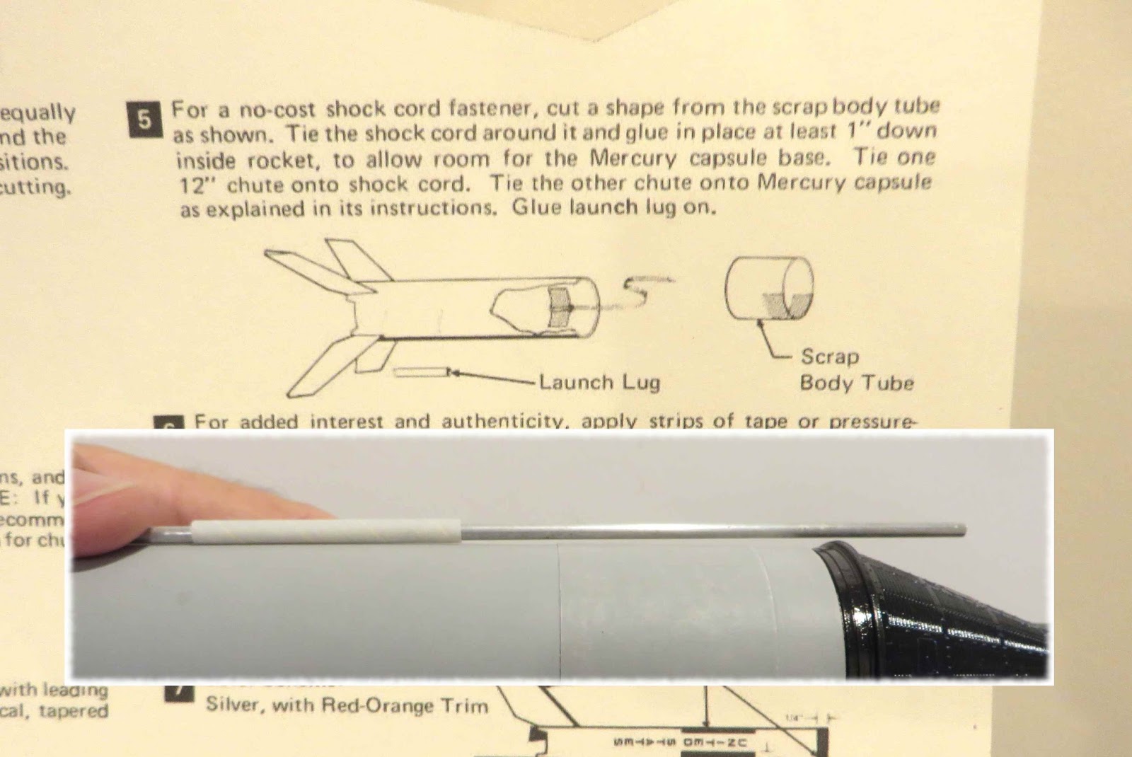
The instructions show a launch lug glued onto the body side. The problem is the widened base of the capsule.
In the picture you can see how a launch rod would rub against the capsule base.


Here's the lug and standoff in place. It is in line with the engine hook.