Saturday, March 30, 2013

Fixing A Fin Ding TIP

On it's first flight the Quest Cobalt had a hard landing in the street
I was expecting big damage but there was just a nicked fin.

Here's one way to re-paint without respraying the whole model.
The fin edge was filled with CWF and sanded smooth without removing much blue paint around the filled area.

The model was masked without pressing down the edges of the tape.
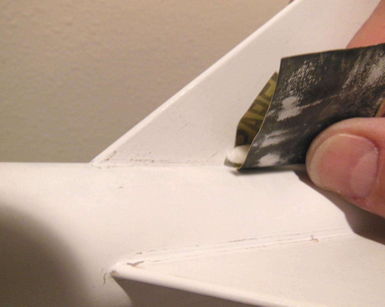
The tape edges were peeled back almost like flower petals. The inset picture shows the view from the front.

Masking this way prevents the new color from forming a hard edge.
Shoot the paint directly from the side, not down or at an angle.


A little of the sprayed paint will get into the lifted "soft edge" and will feather in with the original coat of paint.

This picture Shows the gray primer shot first.
The tape was peeled back to show the soft blend.
Sand the primer lightly, not going down to the blue underneath.


The tape was rolled back up before the blue was shot.

Here I've pulled back the tape to show the blue blend.


After the new paint has dried, use a little polishing compound to polish the soft blend area.
The over spray line (at the tape soft blend) won't be as glossy as the earlier paint finish. The polishing compound should help bring back some of the gloss.

It's not perfect, but better than it looked after the hard landing.

Centurion Project Part 2 Engine Mount Parts


Here's the rings and motor mount tubes for the three engine mounts.
From left to right:
Single 18mm, Two engine 18mm and the single 24mm parts.
These two engine cluster rings are available from Semroc.
I used the rotary punch to allow movement of the engine hook.

The left lower ring has a larger recess for the bottom of the hook.
The right upper ring has been slightly punched for the upper end of the hook.

Friday, March 29, 2013

Rounding Fin Edges

Sorry, no posts yesterday - blame the slow, crappy ship internet connection.

I'd read on The Rocketry Forum where some have had problems rounding fin edges.
Some on TRF were looking for a specific tool that could help.
No tools are needed, just a sanding block and some 400 grit sandpaper.
If you use 400 grit you'll only take off a little at a time. You can correct things before too much has been sanded off.

If you just sand back and forth over a leading or trailing edge, you run the risk of rounding off the square corners of the fin.
Use some 400 grit on a sanding block for more control.
Again, don't just sand back and forth, Set the block on the edge, then sand.
Roll the block around and over the top keeping it flat against the edge.
The block goes over the top as the fin slides down the block.

Make a single pass and check the fin.
Set the block squarely on the fin edge again and make another pass.


When you've got the fin edge rounded go very lightly over the middle of the edge with a piece of scrap 400 grit.
Sometimes when sanding with the block you will sand more off the sides leaving the middle a little square.
Depending on how well you did with the block this step may not be needed.


Here's a good example of rounded leading and trailing edges.
Sight down the fin from the root and outside edges to check the roundness.

The grain is ready to be filled.

Centurion Project - Part 1 Interchangable Motor Mounts

Before I start the next build, check out this past blog post about Marc Goldstein's interchangeable motor mounts: HERE

I'm using his locking, interchangeable motor mount design on my Semroc Centurion builds to follow.

This is going to be a three model build.
The first "Centurion" was finished earlier, the Estes Cosmic Explorer. It's a BT-55 design based on the older Centuri Centurion.
The second Semroc Centurion will be built stock with an 18mm motor mount.
The third Semroc Centurion will be stock except for the three different motor mounts:
1X - 18mm, 2X - 18mm and 1X - 24mm.

I'll be doing comparisons between the Semroc Centurion and Estes Cosmic Explorer throughout the build.

Wednesday, March 27, 2013

Centering Rings - DIY! Part 3


I always cut more than I'll need and use the best, finished pieces.

It's easier to stack the rings on the tube and sand them at once for a consistent size.
The ring edges were a little fuzzy. These mounts will also be removable.
I decided to harden up the edges with some medium CA glue.
The CA will seal the edges.
On a removable mount, these outside edges won't be glued into the tube. So a hard, smoother edge in this application is a good thing.

CA was applied with a Q-Tip and sanded smooth, still retaining a sliding, friction fit in the ST-16 tube.


Here's a good fit of the ring in the mainframe tube.
Certainly not as clean as a laser cut ring, but probably stronger. The framing mat cut rings are thicker than a typical ring supplied with a kit.

Tuesday, March 26, 2013

Bad Engine Hooks

While picking out engine hooks for the Centurion Project I ran across a few engine hooks set aside from past kit builds.
All of these will be thrown away - they're garbage!

If you bend an engine hook and it doesn't spring back, toss it. After the first time you pull these back to inset an engine, it's bent with no way to straighten it out. At ejection the engine might eject instead of the parachute!
When buying engine hooks, be sure they are made of spring steel.
Why not make some of your own from the metal strips inside discarded wiper blades?

Centering Rings - DIY! Part 2

Here's an email tip from Brian Coyle with a better way to center the interior tube circle: 

Here's a tip to help align multiple circles when using tubes like you're doing on the blog (instead of a compass).
Draw cross hairs on the CR material.
Use a 4 fin wrap to mark the tube
Align the tube using the markings
Rinse repeat for the second circle.

Thanks Brian! I have done it this way before with great results. For whatever reason I simply "eyeballed" the interior tube and traced around it this time.


Check the fit on the motor mount tube before sanding smooth the inside diameter.
This is just a small piece of 220 grit to smooth out the rough edge.


Sand a bit, check the fit!
You'll want a friction fit on the inside tube.

I still haven't cut out the outside diameter of the ring.


The outside circle is much easier if you have good, sharp scissors.

Here again I am cutting just inside the pencil line. This line was traced from outside the mainframe tube. Of course, it needs to slide into the tube so it is cut slightly inside the line.

Monday, March 25, 2013

Centering Rings - DIY! Part 1

I need some "non-standard" centering rings for an upcoming build.
A series of three interchangeable engine mounts will be made for a Semroc Centurion.
I don't use BT-20 tubes for 18mm engines, they are too thin and weak. ST-7 tubes will be used.
No BT-50 tubes for the 24mm mount, again too thin. I have some thick walled BT-50 tubing.
The Semroc Centurion uses a Centuri style ST-16 mainframe.
Sure, I could put in a custom order, but sometimes it's quicker and cheaper to just make your own from scrap framing mats.

I don't have a circle cutting compass. I know, I should have one. These rings will be cut with a new #11 X-Acto blade.

Trace around the larger diameter tube first. You won't be able to visually center the large tube if the smaller motor mount tube circle was drawn first.
Use a sharp, thin mechanical pencil.


With the larger tube diameter drawn you can center the inside tube circle inside of it.
Draw and check the center circle. If it's off, erase and redraw.
It might take a few tries.
TIP: Cut the smaller inside circle first!
You'll want to have plenty of border material to hang onto.

Here I'm cutting a little inside the pencil line.
The traced line was drawn around the outside of the tube. You have to make allowances for the thickness of the pencil line next to the outside diameter of the motor mount tube. You can always sand to a perfect friction fit.

Sunday, March 24, 2013

Centurion Project Cosmic Explorer Finished


While I still like the wider girth of the original Centuri (Semroc) Centurion, the Estes Cosmic Explorer looks good.
I don't like the Dymo Letter Maker font name decal and the fins surface seems big for this BT-55 tube.
TTW fins on a LPR rocket? Unnecessary but alignment is easier and laser-cut anything is a good selling point.
The decals are tricky to piece together, plan ahead and be sure you know where each red strip goes.

Be very careful with the red coupler, the dry fit in the BT-55 tube was too tight! Too many have had problems with a red coupler freezing up when being glued in.
The 18" diameter parachute seems a bit big, it'll probably get a spill hole,.

Saturday, March 23, 2013

Centurion Project Part 10 Cosmic Explorer Upper Body Paint Problems

I should be done with this model by now! I had problems with the Rusto 2X Gloss Black.

I did my regular two light coats followed by a heavier "wet" coat.
The final thicker coat crazed and wrinkled!
Who knows why? The weather has been cold one day and warm the next. Maybe I didn't wait long enough for the undercoats to dry.


When sanding down the wrinkled surface, some of the paint layers rolled up!
I continued to sand it as smooth as I could get it.


Three coats of filler / primer followed, sanding between coats.
This raised the lower dips and peeled area.

The upper body and nose cone are ready for the second try of gloss black.

Friday, March 22, 2013

Centurion Project Part 9 Cosmic Explorer Fin Decals


The edges can be trimmed off with a new razor blade.
Use a light touch, just enough to cut the decal film and not into the fin.


The trimmed fin decals leading edge is at the top.

The inset picture shows the trailing edge.
All the decals got a sealing with some Future applied with a Q-Tip.

Dip the Q-Tip into the Future, dab off the excess on a paper towel and apply over the decals concentrating on the edges.
If your finish is good and very glossy, applying Future over the entire model isn't needed. I only apply it over decals that might crack and lift.

When the Future is applied you can see the decal "seat" better on the painted surface. The red color looks richer after the seal coat.

I know - many builders have great results brushing Future over the entire model. That doesn't work well for me.

Thursday, March 21, 2013

Centurion Project Part 8 Cosmic Explorer Fin Decals


The supplied red fin stripes aren't long enough to sit centered on the fins as shown on the face card picture.
Luckily the fins are tapered, the outside edge is shorter than the root edge.
I kept sliding the stripe away from the root edge until it spanned from the leading edge to the trailing edge.
I cut a piece of card stock for a baseline template. By using the template, all the four stripes will be parallel with the root edge and vertical.

I guessed at the height of the template and was wrong.
It reads 1 9/16" away from the root edge but should have been 1 11/16" tall. Still, it helped to align the fin stripes.


Four fin stripes are provided.
I had built a Semroc Centurion a few years ago and thought the red stripes went on both sides of the same two fins.
After looking at the old Centuri instructions I could see one stripe went on each fin. One stripe on each left fin side.

The ends of the stripes are squared and should be trimmed after they have dried. Don't trim them before they dry, they are too flimsy when wet and you'll get a rough edge.

Tuesday, March 19, 2013

Centurion Project Part 7 Cosmic Explorer Decals


The Estes instructions are very vague about the red stripes decals and their placement. The face card barely shows the long red stripe down the lower white body tube.

For a better reference I went back to the 1972 Centuri catalog. Enlarge the picture and you can see the long stripe on the bottom edge.


Here's the decals included in the Cosmic Explorer kit.

Going counterclockwise, starting with the nameplate decal.
(I don't understand the font choice in the nameplate. It looks like an old Dymo Lettermaker strip!)

Immediately below the nameplate decal is a red strip about 4 3/8" long.
This is the horizontal band (below the upper black tube) that goes around the tube.

Beneath that are the long stripes (8 1/2" long) that go vertically down the tube. The long vertical stripes are made with two pieces. The upper pieces (3" long) are on the middle right side of the decal sheet.

The four shortest pieces (2 1/4" long) go on the fins.

Plan ahead before even thinking about soaking the decals!
The nameplate will have to go on the opposite side of the launch lug.
The long vertical stripes go above and blow the nameplate decal centered between two fins.

The longest vertical stripe goes on first from the bottom and up.

Sight down the tube to be sure it is straight and centered between two fins.
With the longest stripe piece (8 1/2" long) even with the end of the body tube it won't be long enough. Piece the 3" long piece on top of that.


This leaves about 1/2" from the top of the white tube piece.
The horizontal stripe (4 3/8" long) caps off the vertical stripes.

The picture at the right is just for reference, the horizontal stripe should overlap the vertical stripes.


With both vertical stripes in place you can better center the nameplate decal.
Center the round compass between the stripes

Monday, March 18, 2013

More MPC (SKY) Rockets


The Round 2 Company is refacing more of the Chinese Sky rockets with a Looney Tunes theme.
All three carry the "Duck Dodgers" name.


The Marvin Martian themed rocket is really the Sky Rockets "scale" Shenzou.


And finally, the Porky Pig model.
So far, build comments on forum posts haven't been good.

The models should be available after June, 2013.


Launch! Schoolyard March 17, 2013

I leave for a two week cruise later today so this morning was my last chance for a Soccer field launch!
Yesterday morning the field was being watered and was full of soccer players. Today the field was clear!


The Estes SUPER ALPHA was first up with an Estes B6-4.
This is really a great match for the small field - a BT-60 model with an 18mm engine.
Perfect flight and recovery.


The FlisKit 13mm UFF ATHENA flew to about 75 feet with an A10-3t engine.
Fun to watch - labored boost, turns over and floats down landing on the wire antenna legs.
Still, it feels like a wasted engine. I want to say: "More Power!" but the A10 engine is all you've got!

This was the first flight for the FlisKit PHEORD X150 saucer.
Another great small field model with an Estes C6-0.
While the web page says it gets up to 75 feet, it looked like closer to 200'.
When the booster burned out, the propellant wall broke through and you could see the sparks. This was early enough in the morning and the sun wasn't fully up yet.

This is an 18mm upscale of the UFF Athena with redneck graphics.

My highest flight today was the reinforced Custom SOLAR EXPLORER with a Quest B6-4.
Altitude looked like about 450'.
This one did drift and landed in the street.

While the parachute did eject, the wadding was still inside the body tube.
I'd hate to think it might be smoldering inside!
If one of you models had to land on asphalt, this it the one! The engine extends past the trailing edge of the fins and there was very little damage.

Also Flown:
MPC TAURUS with an Estes 1/2A3-2t engine.
Small models always look like they get better altitudes than they probably do. I'd estimate the altitude at about 275'.
The shock cord didn't hold and the body separated. The nose cone came down on the parachute, the body landed easily without damage. Time for a repair!

Sunday, March 17, 2013

Centurion Project Part 6 Cosmic Explorer Paint

The Titebond M&TG fillets had some slight ridges you could see once the white paint was applied.

To sand the tight angle in the root edge wrap some 400 grit around the end of a Q-Tip.
The cushioned end of the Q-Tip allows the sandpaper to roll into the root edge without creasing. Sharp folds in the sandpaper could scratch a line into the fin.


After the next coat of paint had dried, the tape covering the engine mount was removed.

The back edge of the body tube had a rough paint edge.
400 grit was used on the inside lip and over the edge.

I painted the lower half gloss white and the upper body tube and nose cone gloss black.
If you didn't glue the body tube sections together you could paint the two colors separately then glue it together - no mask needed.

No Launch! Saturday, March 16, 2013

I walked over to the soccer field about 7:00 a.m.
Here's what was waiting for me - Soccer players and sprinklers!
The parking lot was full of cars which leads me to believe the men on the field don't live in the neighborhood. If they lived here they would have walked to the park.

It's a resident use area, every homeowner pays monthly fees for the right  to use of the small park and field.
These teams have been asked to leave before. The maintenance men have told me that after a game they pick up food, empty bottles and diapers.
I wasn't going to tel tell them to get off "my" field to fly rockets.
Besides, the field was wet anyway.

The Tampa TTRA launch was today, but I decided not to go.
It's maddening to travel that far (Roger Smith usually drives) pay $5.00 launch fees when only two out of the four LPR launchers work. Sorry TTRA, that's just my 2 cents!
There are great people and it is a big field, tho - 

Another reason for not going to the TTRA launch, I'm leaving for a two week cruise on Sunday, March 17. Last year was a good one for work and shows, but my blog posts have been harder to keep up with. If I miss a blog post a day or two over the next two weeks it's because of the crappy ship internet connections.

Saturday, March 16, 2013

Centurion Project Part 5 Cosmic Explorer Fin Primer and Gluing


The fins are test fitted in the TTW slots.
Even with the slight thickness of sanded wood filler (CWF) it was a tight fit getting the fins seated.

I'm not gluing the fins in place yet. The slots will hold the fins in place for primer spraying.

By not gluing the fins in the slots I can remove them to sand the primer down. It's easier to sand the primer when you are not dealing with the angle of a root edge.

In the picture you can see I have an automatic mask - no primer is on the TTW tab or the root edge gluing area on the body tube.


After the primer coat it took even more forward and back wiggling to get the fins seated.
Check the root edges of the slot to be sure they sit squarely against the fin sides.