Showing posts with label Fin Slotting. Show all posts

Sunday, September 24, 2023

Estes Black Brant XII, Kit # 9723 Build, Part 10, Cutting The Fin Slots


Mentioned earlier,
Check the fit of the fin slots with scrap balsa left over from the balsa sheets. Note the low fins are thicker than the 2nd stage fins.


The molded third stage fins fit into the highest slots. If the slots were cleanly cut, the fin tabs will almost snap into a tight fit.


The blow molded parts are cut apart and the ends cut off.

TIP: To be sure I was cutting on the correct lines, I drew a black line using a fine point Sharpie. Look close at the bottom of Page 3 and double check before cutting.


Square up the rough cuts with a block.

TIP: Round the edges for a smoother slide (less wear) in the body tubes.

Saturday, September 23, 2023

Estes Black Brant XII, Kit # 9723 Build, Part 9, Cutting The Fin Slots


The raised fin locations are cut off leaving a open slot for the central fin tabs.

Score down the sides, stopping at the rounded ends.
Use a new sharp blade. Don't try to cut through with a single pass. It will take a few passes to cut through the plastic.


Cut through the ends.
The raised rib should come off.


Here's what the rough cut fin slot will look like. It will need to be cleaned up for a good fit of the central fin tabs.


I did some squaring up of the lines using my aluminum angle.

Constantly check the fit of some scrap balsa, the same thickness as the TTW fin tabs.

Wednesday, November 2, 2022

Estes Odyssey #7235 Build, Part 10, Cutting The Tube & Fins Slots


The large marking guide wrapped and fit the large tube perfectly.

Notice that only three slots are cut through the tube wall (TTW), the TB, TC and TD slots.
The other long rectangles, TA and TE are only to be marked with a pencil. The TA and TE rectangle markings are for the smallest surface mounted fins. 
I'd recommend cutting the end curves before cutting the thru the wall slots. The tube is stronger before the tube slots are cut.

As recommended by John Boren - use a new sharp blade. Don't try to cut through with a single pass. It should take 3 or 4 cuts to go through the tube wall cleanly.


I used a metal ruler edge for straight lines.

It's not easy to hold a long metal ruler still when making the cuts.


The ends were cut by punching the tip on one side, then turning over the tube and punching the other corner - meeting in the center.

Tuesday, February 1, 2022

Rocketship Games Alice's Star Rocket #R6, Part 4, Assembly Prep

I waited until after the filler/primer was sanded to remove the fin slots pieces.

With the launch lug slid in the longest slot, the fin slots line up perfectly. 
I tested the fin fit making sure the rounded leading edge on the fins was facing up. It's a good friction fit "grab" in the slots. Be sure the leading edge is facing up - or the outside edge could end up scarred.


Here I've set the fins onto sticky side up tape for the white undercoat.
Spray one side, let dry.
Flip over the fins and spray the other side.


The Kevlar shock cord is tied onto the attachment point at the top of the engine mount.
The long, loose end is tucking inside the mount and trails out the back for gluing into the body tube.


The face card shows the launch lug in a different color than the main body. I thought that drew some attention to the launch lug. I sprayed it while slid in place the same color as the body.

Monday, July 26, 2021

Estes DARC-1, #7307 Build Part 4, Clearing The Fin Slots

The fin slots have to be cut from the blow molded conical body.
First things first - Start with a new, sharp blade! 
Take your time - don't attempt to cut through the plastic wall with one pass. 

The widest sides of the conical body have the thinnest plastic wall!.
The fin slot area plastic is thin. Go light with your knife, you could go through the plastic when you don't expect it.

Notice the pencil line I drew around the raised fin slot before doing any cutting. The pencil line will help visualize the edge when cutting.

I don't normally use my X-Acto knife with a #11 blade, but I will on this cutting chore. I want more control than my break-off blade knife. 


If anything - cut the slots a bit smaller than needed. You can (and will) widen the slots to fit the fin thickness.

Even cutting right at the sides of the long raised hump, the cut slot is inside the pencil lines.


You could shave the sides with a knife blade, but I found more control using a small flat diamond file.


Use a scrap piece of the balsa sheet to check the fit of the fins. 
TIP: Don't use the kit fins to check the width, you could scar them up doing test fittings.

Wednesday, February 5, 2020

Quest Future Launch Vehicle #3013 Build, Part 10, Slotting The SRBs


Here's the three SRBs with the dry fitted.

Before gluing the nose cones in, line up the open areas of the wraps, as shown here in the middle SRB.
To cut the fin tab slot through the wrap -
Press the fin slot area with a fingernail.
I didn't remove a long rectangular piece from the wrap.
A single line is cut, centered down the slot. In the lower picture - On the ends cut two short vertical lines making an elongated "H" shape, like this -     I----------------I.
When the fin tab is pressed in, the long sides will fold in making a tighter fit.


Here's one of the fins dry fitted into the slot. I glued them in after the SRBs were glued onto the body.
On the very sides of the root edge you can still see the outside of the words: "GLUE FIN HERE".


Monday, February 3, 2020

Quest Future Launch Vehicle #3013 Build, Part 8, Smaller Wraps


You can use a glue stick to adhere the smaller wraps that are placed on Kraft tubing.

The motor mount tube gets a nozzle wrap. Test fit it dry - without glue to see how it is spaced around the engine hook.

The rear centering ring was blacked using some Sharpie pens.


This isn't necessary, but I wanted the launch lug seams covered.
There is plenty of white scrap left from the large wrap sheets.


Don't cover the entire lug, I leave a side open for gluing onto the main body.


This shows how thin the print wrap sheets are. Be careful, you can easily crease them.

Saturday, January 13, 2018

Model Minutes Leduc 22 Build, Part 15, Rear Fins and Body Slots


If you glue the fin tabs directly onto the printed lines on the interior tube, they don't rest against the rear centering ring. I assumed this is what the designer meant to do.


Here's what the main body assembly looks like up to this point. Three rear fins are glued on and two centering rings are also glued onto the interior body tube. Both the centering rings are centered inside printed lines on the interior tube.


The two main wing sides are joined in the center. The wing slides all the way through slots in the interior and outside rolled tubes.

The slot is cut in the interior tube. The tube is floppy but the slots can be cut with a new blade. Cut the top and bottom slit first, then the long vertical l


There is no good way to fold the slot sides inside the body. I used my long tweezers pressing the tabs and getting as sharp a fold line as I could.

Monday, June 19, 2017

Estes Apollo Little Joe II Build, Part 17, Fin Support


Here's the final stick size - Your fit may be different. Cut a little large and fit to your model.
The overall length is 2 11/16" with the taper starting 1 5/16" from the end. The tapered end to the right fits into the fin cavity.


The instructions don't mention it but imply the rear centering ring is even with the end of the body tube.
On the actual Little Joe II the nozzle plate was slightly recessed. I could build up the inside so the rear centering ring is closer to the bottom of the tube but will probably leave it as is.
This picture was posted by John Pursley in the TRF build. 


I'll be following John Pursley's advice and make the nozzle plate and centering ring removable. Some flights have shown some melting of the plastic nozzles.

With the rear centering ring against the square fin supports it's a very strong assembly.

Again I can't take credit for using a fin reinforcement spar. The master modeler's at The Rocketry Forum - George Gassaway, James Duffy and John Pursley figured out the structural improvements.

The fins are probably fine without the stick reinforcement. I've read a few launch reports where a fin has been knocked loose from the corrugated wrap on a hard landing. Plastic to plastic bonds between the fin and the body are sometimes a problem.

Estes Apollo Little Joe II Build, Part 16, Fin Support

I used a new #11 blade in my X-Acto. You'll be cutting through the body tube and wrap plastic. My usual break-off blade knife wasn't used for these cuts.

Note the knife tip position set into the corners. I punched through all eight corners and then cut through the centers. This way the back of the knife worked like a "stop" and prevented me from cutting outside the square.


I cut a little inside the drawn square and then trimmed it to a friction fit of the stick.

After cutting one square I checked the fit of the fin position. All was good so the back edge was measured. Using the 3/16" square stick, the rear of the cut square was 9/32" from the back edge. The other three squares were marked and cut.

Note the engine mount was slid in to support the tube during the square cutting.

The inset shows some of the tube pushing in around the stick. I wanted a fairly tight fit around the support stick.
On the left is a pencil mark where the stick will be cut to glue to the engine mount tube. This will be cut slightly long and trimmed to fit.

Sunday, June 18, 2017

Estes Apollo Little Joe II Build, Part 15, Fin Support

Well, I left out the post on the Fin Half Gluing. I've re-numbered the blog posts, scroll down to see a new post at #13. Everything should be in the correct order now.

The Little Joe II fins are surface glued on a vacu-form wrap, probably not the strongest joint. In post #229 of the TRF build, John Pursley showed an improved fin reinforcement. CLICK HERE

The first time he used a tapered wood dowel that went in the fin interior, through the body tube and glued to the side of the engine mount tube.
This revision used a square stick, Much stronger and the flat side lays against the right centering ring below it.
This allows the model to be flown without the nozzles if the lower ring and nozzle assembly is not glued in. Some flight reports have mentioned some melting of the plastic nozzles.The four square sticks will be very strong and also center the engine mount tube without the lower ring in place.

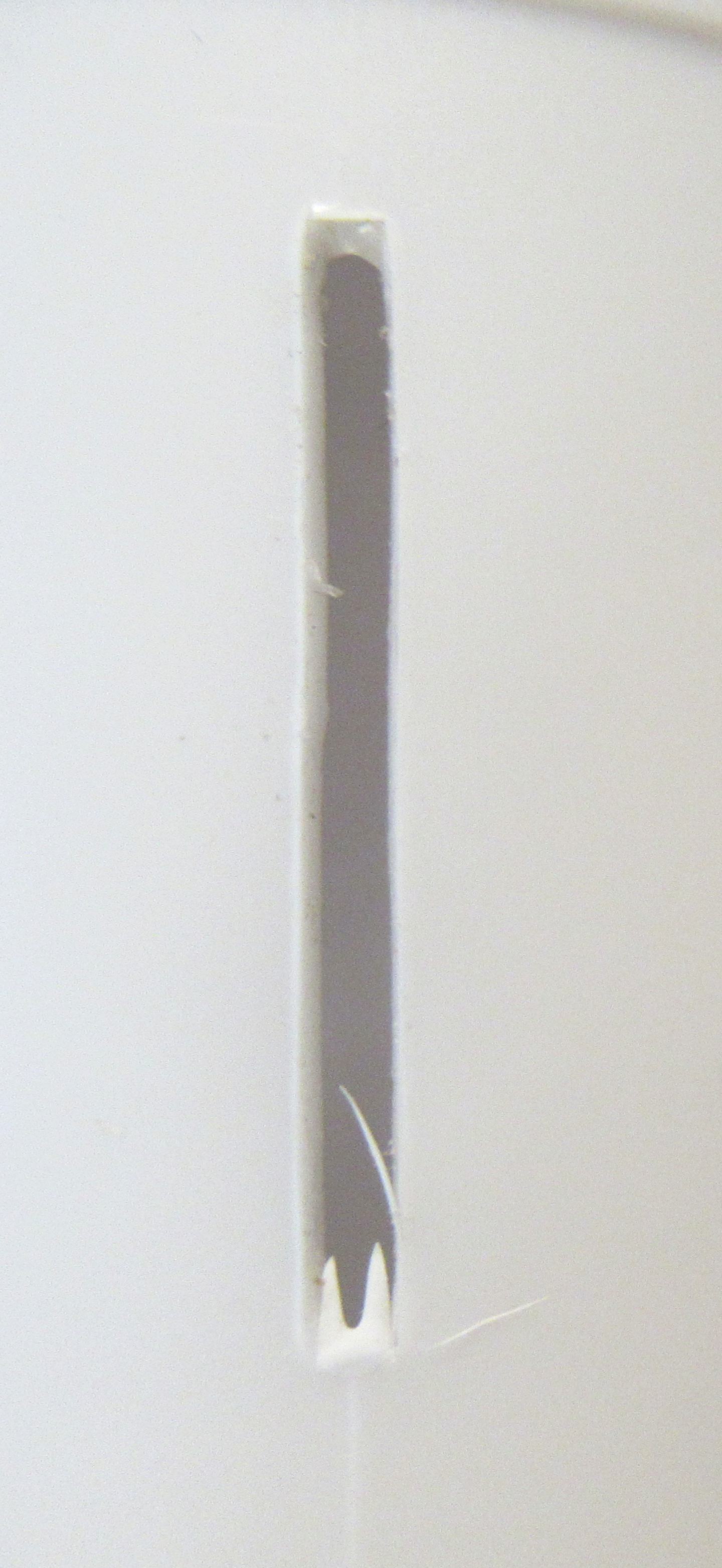
John Pursley used a 1/4" square stick, mine was 3/16". The length to start is 3" long. It'll be trimmed to fit later. Right now I'm just trying to get the taper to fit the inside of the fin.

The inside taper starts about 1 5/16" from the end.


Held up against a light you can see stick inside. It won't go all the way to to the outside edge. Don't press too hard or you could split the fin right down the glue line.

Fit the fin without the stick and you'll see the back edge is slightly above the end of the wrap. Take this into account when marking for the stick cut.

Rough up the wrap inside the fin guides with some 400 grit. A pencil won't write on the smooth plastic.
Press in the stick and set the fin on the body sideways. Trace the top and bottom of the stick with a pencil.

Tuesday, November 17, 2015

Estes Honest John, #7240 Build, Part 3, Tail Cone


The instructions are vague about how to cut the fin slots, just a knife and some arrows.
Instead of trying to cut around the corners with a knife tip, I rolled the blade back and forth underneath the rounded end.
Please note: I'm not carving away the entire raised rib. I'm just working around the rounded ends
Then cut the long sides. It's pretty easy to cut down the raised rib.


Most of the slots cut clean except for one.
The inset picture shows the slot with the rough edges.


The slots were cleaned up using a flat file.
Don't do what I did, I opened up the slots a little too wide. The center TTW tab of the laminated fins is only 1/16" thick.

Tuesday, January 24, 2012

Scavenger! Build Part 17 Fin Gluing

When you thing about it, Through-The-Wall or TTW fins really changed the structure and strength of mid and high power rocketry.
When I started in 1969, all model rocket fins were surface mounted. For low power models it was fine - for the most part.

The Scavenger fins are Basswood. The interior fin tabs lock against the lower thick card stock centering ring on the engine mount. That and gluing to the engine mount tube gives you a very strong fin can "unit".


Initially 15 minute epoxy was mixed up and applied on the root edge of the fin tab.


The fins were inserted into the slots.

With the 15 minute epoxy set time, I was able to come back every few minutes and check the alignment until I was sure the glue had set up and the fins were tight against the body tube. Even with epoxy on just the root edge tab, it's a very strong joint.

Sunday, January 22, 2012

Scavenger! Build Part 14 Root Edge Fitting


Here's the fin fit after the trimming.

Adding the extra recess for the wrap of tape on the engine mount made a big difference in getting the best fit.


With the rear fin in place, you can now see how they'll both look together.

Saturday, January 21, 2012

Scavenger! Build Part 13 Root Tab Fitting

With the fins slots cut the engine mount was slid into position.
On this model, the end of the engine mount tube and mainframe tube are even.

A ruler was slid into the cut fin slot. With the end of the ruler making contact against the BT-50H engine mount tube read the measurement of the ruler.

This shows the thru-the-wall fin tab will need to be around 1/2" long.
I purposely cut the fin tabs longer than needed so they could be trimmed and sanded to fit.


The fins were marked with a pencil.
The TTW root edge line was drawn parallel to the lower mainframe root edge line.


I ended up sanding off the excess tab with 100 grit sandpaper on a block.

I also added a slight recess for a better fit over the tape wrap on the engine mount.