Showing posts with label E Long Tom. Show all posts

Wednesday, February 8, 2017

Sprint XL and Long Tom Builds on Ebay


For the next few days, both the finished Sprint XL and Long Tom builds 
are up for auction on Ebay!
The Sprint XL is HERE, The Long Tom is HERE
Stop by, make a bid and support the blog!

Those high shipping costs has been adjusted and corrected . . .

Monday, January 9, 2017

Long Tom Fins - The Final Word!

With most all of the JimZ instructions back and available for viewing, I could finally check the Centuri Long Tom instructions to check the sustainer fin placement.


While this step doesn't say the rear of the fins are even with the end of the tube, the illustration shows they are!


Later in the instructions this is shown.
Good, I'll sleep better tonight!

Tuesday, December 20, 2016

Centuri Long Tom Face Card - FINS!


After the post about the Long Tom fin position, BAR Geezer added a comment:

"Did a little digging and I found a good picture of the original Centuri face card here:
http://aeroconsystems.com/cart/rocket-kits/centuri-long-tom-out-of-production-rocket-kit/
As you can see, the sustainer fin root end seems to be even with the end of the sustainer tube. So rest assured, your build does conform to the original Centuri model."


Here's the picture from that listing.
It's low resolution. 


I clicked on it and got a larger picture. Here's the close up of the sustainer fins.

They are glued even with the end of the upper body tube.
Whew! The things BARs obsess over.

The plans at JimZs and the Wayback Machine site won't open.

Saturday, December 17, 2016

Estes Long Tom, Follow-Up - Sustainer Fin Locations?

At a recent Orlando R.O.C.K. launch, Glenn S. launched his Estes Long Tom.
I looked at the fins and wondered why they were positioned up from the end of the sustainer body tube.


On the left is my finished Long Tom. On the right is Glenn's model. Notice the upper stage fin locations?
Glenn said this was his second Long Tom build. He noticed in the instructions that it showed the fins glued on up from the rear of the body tube. His second build had the raised fins.
I read and follow directions and wondered how I could have missed this.

Earlier in the instructions you are instructed to mark the fin locations with a wrap around guide.
No mention is made to make a mark 1/2" or so above the low end of the tube.

The fin gluing illustration in the middle of page 4 shows the two fins marked "J" above the tube. Look at the straight on view of the middle fin. It looks to be even with the end of the body tube.

The inset picture is from a later step in the instructions. The trailing edge is even with the end of the tube. Most all other drawings show the same fin position.

Here's the face card illustration.
The back end of the second stage is black but you can make out the fins are glued on up the body tube.

The Estes instructions are inconsistent. Is it a big deal, does it effect the flight? Probably not.
If you wanted to build it closer to the old Centuri version it's a little maddening.
I went to double check the instructions on the JimZ site but many of the Centuri plans don't come up.

Friday, December 16, 2016

Estes Long Tom #3016, Finished


When you break it down, the Long Tom is simply a tall two-stager.
It wouldn't have the same feel if the upper tube were gone and a nose cone topped off the larger tube.
It's an impressive model even flown as a single stage.

This one did get some upgrades. The black paint is the Rustoleum Black metallic. Rather than paint all four fins black, I left two white so the red decals could be used on both sides of the fins.

If it ever gets flown I'll take John Boren's advice and made sure the stage coupler fit is very loose.

Thursday, December 15, 2016

Estes Long Tom #3016 Build, Part 16, Booster Comparison


Here's how the booster came out.
It still reflects the Centuri paint styles from when the kit came out in the 1970s.


The inset picture shows a part of the face card art.
The back end of the rocket had a lot of black. I didn't feel like masking four fins anyway.

Wednesday, December 14, 2016

Estes Long Tom #3016 Build, Part 15, Booster Decal Cheats

Here you can see the kit only supplied left side fin stripes.

TIP: I picked up a trick on the Estes QCC Explorer build. Estes only supplied decals for one side of the intakes. Someone on the forums slid the decal off the backing sheet and flipped it over, laying it top side down. The adhesion wouldn't be as good but with a clear coat of Future the decals will stay in place.


That seemed like an easy way out on this build.
The overlap rolled over the rounded leading edge joining the stripes at the top. The invisible clear border was rolled over and past the leading edge.


Future clear coat was applied with a Q-tip.

Don't roll over the clear edge at the bottom. After the decal dries carefully trim off the clear with a sharp knife. Follow up with Future on the edges.

Tuesday, December 13, 2016

Estes Long Tom #3016 Build, Part 14, Booster Decals


This is the booster after sanding down the rough spots of the first white coat.
Hold the model up to a bright light and look for glue boogers and any raised areas in the fillets.


After the paint had thoroughly dried I checked decal placement.
The red fin stripes didn't have a white undercoat so they'll go on the white fins.
I thought the kit supplied right and left side decals but there were only left side stripes.
Hold the decal over the fin against a bright light to find out where it will sit on the fin. Allow for a small overlap on the top and bottom.


The left sides were applied first
I drew a pencil line down a piece of card stock to use as a spacing template. With the side of the card stock against the root edge the spacing was checked at the top and bottom of the stripes.

The top ends rolled over the rounded leading edge with the red ending halfway over the top. See the next post for a better picture.

Estes Long Tom #3016 Build, Part 13, Sustainer Decals

The large striped wrap goes all the way to the top of the upper tube.
It's hard to see the the picture but the clear overcoat goes beyond the red and black edge.
The inset picture shows the decal with clear border cut off so it can be positioned all the way to the edge of the tube.


I was curious to see if the decals had any white backing. I slid the Estes decal off the backing and it was clear.
This helps decide what to do with the red booster fin stripes later on. They have no white undercoat so they wouldn't be visible on black fins!

I also cut the TM off the LONG TOM decal. There's no reason (as a consumer) for it being there.
Set the stripe wrap down first. With the long wrap on the upper body you can find the correct location for the next decal.

With a pencil, mark the center of the tube area below the long stripe wrap. Mark the center of the LONG TOM name. Use both center marks to easily position and center the decal.

While  the decal is still wet, double check the position visually, not just by the pencil lines. Sometimes you start with the actual center then slightly adjust the decal so it is visually centered.

Monday, December 12, 2016

Estes Long Tom #3016 Build, Part 12, Shock Cord and Parachute Ties


The Kevlar shock cord is purposely short so it can't cut into the top of the body tube at ejection. The only way to tie on the elastic shock cord is to feed the Kevlar out the back end.

The Elastic is tied on using the low stress loop knot: CLICK HERE


The upper body section is tall on this model.
The elastic has to be extra long so the upper body won't swing into the lower section during recovery.

Before tying a loop knot for the parachute snap swivel, hang the body so you can see how long the elastic should be.


Here's the upper end of the elastic.
The parachute snap swivel loop goes a little closer to the screw eye on this rocket.

Saturday, December 10, 2016

Estes Long Tom #3016 Build, Part 11, Screw Eye Install


To the left is the screw eye supplied in the kit. The threads are too small to effectively lock into the balsa adapter.

On the right is the screw eye I replaced it with. It's the same length but the threads are wider.

At club launches I see ejection separations where screw eyes pull out of balsa.


TIP: For a straight screw eye install - go slow.
Screw the eye in one full turn, stop and check for straightness.

If it's crooked (like on the left) push it up straight then continue screwing in another full turn. check again.

As normal, remove the screw eye and squirt in some glue. re-inset the screw eye.

The pictures show a straight, strong install.

Friday, December 9, 2016

Estes Long Tom #3016 Build, Part 10, Black Paint


To be sure paint doesn't get in the back end of the sustainer-
first small pieces of masking tape are set inside and around the tube end.


A strip of paper towel is rolled up and pushed into the recess.
Tweezers are used to push in and position the paper. Try to get coverage over the engine holder tube.


On the left is the mask before painting.
On the right is after the masking tape is removed.

I used the Rustoleum Metallic black. This paint is a favorite. I goes on smoothly and has a very small metal flake.


Uh-Oh! Paint problems!
Florida is cooler now and painting should be easier. Today is overcast and looks like it might rain.

TIP: The paint dried cloudy not shiny!
I let the paint fully dry and used polishing compound to buff out the haziness.
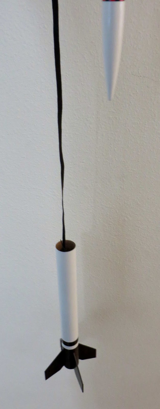
Look at the top fin in the picture. For comparison, the top outside of the fin was left hazy. The lower root half has been polished and is much shinier.

Thursday, December 8, 2016

Estes Long Tom #3016 Build, Part 9, Sustainer Paint Mask


On the forums, some builders do three or fours coats of primer / filler, sanding between coats. I don't think that's necessary and adds quite a bit of weight to the rocket.

After filling the wood grain with one application of CWF and sanding, I only need one wet coat of Duplicolor Primer /Filler. The picture shows how it looks after sanding. Most all the primer is sanded off. Any grain pores that remained are now leveled off with the primer.


Here's how the instructions lay out the masking.
Most all the rocket is gloss white. The low end of the sustainer and booster fins are black.

I used a 3/8" wide Scotch tape strip for the horizontal white band.
The end is slightly tapered so the squared end won't mask a small corner tick at the end of the wrap.
Note that the launch lug is below the mask. The lug was glued on lower than the instructions showed so it wouldn't have to be in the mask area.

3/8" to the right will be another tape wrap. The rest of the upper body is masked off.

Wednesday, December 7, 2016

Estes Long Tom #3016 Build, Part 8, Fin Gluing and Alignment


The launch lug was glued on and got a fillet of Titebond M&TG.

Before shooting the tubes with filler / primer, the fin locations got a thin line of masking tape.


After the primer was sanded down the fins were glued on.

Clothes pins were used to help the alignment of the upper and lower fins.
TIP: Normally a clothes pin wouldn't reach to both fins. These were flipped so the clamping end is longer and flat.
When the spring and wood halves are flipped like this, the end facing the right side has a longer, flat and even clamping area.
To see the full explanation, CLICK HERE

Tuesday, December 6, 2016

Estes Long Tom #3016 Build, Part 7, Lug and Fin Positions

It pays to look ahead to the paint mask location before gluing on the lug. It's much harder to mask over the launch lug.

On the top is where the instructions say to glue on the lug, 1 1/2" from the rear of the upper tube. I marked the tube to show where the black paint will be.

Move it to the back of the tube and there will be no masking over the raised lug.


TIP: To check the accuracy of the fin marking wrap - 

Wrap and mark the fin locations. Here I marked the fin lines 1, 2, 3 and 4.
Now rotate the first fin location (1) on the wrap to the "2" mark on the tube.
Check how the marking guide matches up at the 3, 4 and 1 locations.


TIP: You don't have to mark the booster and second stage separately.
Slide the tubes and continue the marks down the booster using an aluminum angle. This way you are assured the upper and lower fin lines are consistent.

Monday, December 5, 2016

Estes Long Tom #3016 Build, Part 6, Wood and Seam Fill


The fins are pretty interesting.
They don't really "fit" together, the trailing edge of the sustainer fin isn't at the same angle as the leading edge of the booster fin.

The sustainer fins have sharp corners.
The booster fin has two rounded corners.
This was typical of the Centuri designs. They were sometimes out of the ordinary.


The tube seams were filled with thinned CWF.
That's a lot of tubing to fill!


The filler was sanded with 220 grit first. The bulk of the filler was removed.
400 grit took the filler down to the tube surface.

Friday, December 2, 2016

Estes Long Tom #3016 Build, Part 5, Mount and Coupler Gluing


The sustainer engine mount got a Kevlar shock cord tied on beneath the upper ring.

The long end was fed through the engine hook slot.
The loop was pressed into the the glue fillet going around the centering ring.


Both the booster and sustainer engine mounts end up even with the low ends of the boy tubes.
I used the flat side of the sanding block to press the two tubes flush.


Apply glue inside the upper end of the booster tube.
The coupler is pushed in the front end of the booster until it butts up against the upper centering ring.
It actually sticks out farther the instructions show.


After the coupler is glued in, immediately slide the upper sustainer tube in to make sure the tubes are in line.

Turn the upper tube. Remove the upper tube so it doesn't get glued in.

Thursday, December 1, 2016

Estes Long Tom #3016 Build, Part 4, Coupler Prep


For a better slide into the upper stage tube, round off the top edge of the red coupler.

Before doing the CA coat below, test fit the coupler in the main tube. Sand the coupler sides if needed for a easy slip fit.


Slide the coupler into the booster tube and draw a pencil line around the top.

Coat the exposed area above the line with medium CA glue brushed on with a Q-tip.

Sand the dried CA with 400 grit sandpaper.
The treated side of the coupler makes a smoother fit into the upper body tube.

TIP: According to a recent TRF post, the coupler should be a very loose fit in the upper body for smooth, vertical staging.