Saturday, February 29, 2020

Centuri Skylab KB-4 Fin Covering?


Here's a tough one to clone - The Centuri Skylab. That strange plastic nose cone was re-used in a few designs. There are a few vacu-form wraps, nozzles and details where molds would have to be made.

In the Centuri kit, the thick card stock fins were covered in a metallic foil with a tight embossed square grid. They supplied a peel and stick covering.

I just replaced my windows in my townhouse. The rear windows face the West. In the Summer a lot of heat is transferred through upstairs windows, the single pane worked like a magnifying glass. I covered my upstairs windows with a thin radiant barrier ordered through Ebay.

The embossed sheet is shown on the left. You can see the tight square pattern that runs throughout.
On the right side is a scrap piece, turned over and taped to cardboard for some "77" adhesive spray. You can't really see the embossed squares on the backside.

I rounded the leading edge on a scrap piece of balsa.
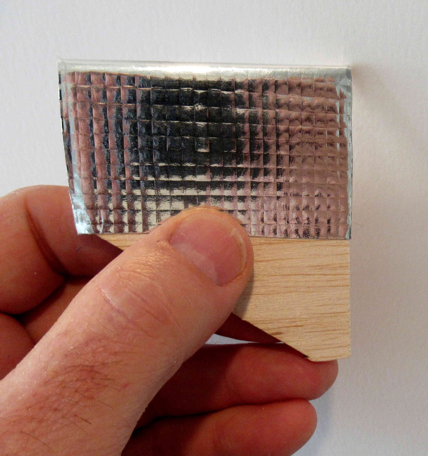
The radiant barrier piece was set down over the leading edge and pressed onto the flat sides.

I was curious if the embossed squares would disappear when the thin foil was pressed down - they didn't! The lines did go away only over the leading edge. This foil could be used on a clone.

Now if somebody would produce the vacu-form wrap parts, I could make a Skylab! Even if you aren't building a Skylab, a embossed panel like this could look like a solar panel fin.

EDIT: I checked some Ebay listings and can't find this same square embossed radiant barrier sheets. The few I see now have small perforations throughout the sheet. Keep an eye out, it's out there somewhere -
Sorry - I won't be selling or mailing out this covering material.

Estes Low Boom SST #7289 Build, Part 6, Jet Engines Assembly

The curved side supports are glued on both sides of the center strut.
After the supports were in the correct position, tweezers held them tight on the sides as the glue set up.


Here's my first CWF pass to fill the tab slot recesses. The picture shows  the side after sanding. I'll have to go back for a second pass of filler and sanding.


I scanned the card stock pieces just in case I had problems. This is a print of the scan. Notice the 1" span reference lines to check the home print.
The middle piece of the verticals is a bit taller than the side pieces. The printed center line is the high point of the card stock top and bottom covers.

DON'T DO THIS - I tried a light crease down the printed line with a butter knife and straightedge. I found out this wasn't needed. See the next post for a better solution.

On the right - I cut the piece a bit large, just outside the printed lines. It will be trimmed after gluing later. Right now, just do dry fits using no glue.
The inset picture shows the soft fold over the higher center piece. The right and left sides of the card stock curve down a little to glue to the top and bottom edges of the side pieces.

Friday, February 28, 2020

Estes Low Boom SST #7289 Build, Part 5, Jet Engines Assembly


Before adding the stringers, the assembly top and bottom were sanded smooth. Use a sanding block here with 220 grit sandpaper.

The small stringer notches are cut square by the laser. These have to be trimmed at an angle for the stringer gluing.
TIP: Use a single edge razor blade to do two cuts at the same time. This will keep the cut angles consistent.


Before cutting all the way down, lightly score the lines with a  to check the width and angle of the cuts.
With the corner angles cut, the stringers are glued in place. Note the left end of the stringer at the halfway point. It is cut at an angle so the the right and left tip centers will match.

This reminds me of the Guillow's planes I made as a teen. There was lots of 1/16" thick stringers and fitting involved.


Here's the stringers glued in place on the front and rear of one engine.


Some inside glue dots were added to the stringer joints. Excess glue was picked up with a Q-tip.

Thursday, February 27, 2020

Estes Low Boom SST #7289 Build, Part 4, Jet Engines Assembly

I'll be dedicating a few posts to the construction of the jet engines. These are the most involved part of the build. 

At the top is the middle piece, below are the right and left sides.
TIP: You might want to fill the balsa grain with CWF before gluing the engine together. It would be difficult to fill the leading and trailing edges (and visible interior) after it is glued up.


Test fit, test fit! test fit, before gluing.

The center struts fit well, I didn't remove the hold down tics left from the laser cutting for a tighter fit of the strut tabs.


The center engine piece shown here is upside down. You can see the sanded CWF filler on the flat face at the front and rear.
The two notches got small drops of glue for the interlocking horizontal struts.
The inset picture shows the struts 90 degrees to the center piece.


The horizontal support struts are glued onto the larger center piece.

After that dries the sides are glued on. Note the tabs are recessed.
I wish the tabs were a little longer so they would extend beyond the outside face of the side pieces. It would be better to sand a longer tab flat and end up with less filling to do.

Wednesday, February 26, 2020

Estes Low Boom SST #7289 Build, Part 3, Gluing Up The Wings

The two piece large wing was glued up against a straightedge. On this pre-production kit, the root edge wasn't quite flat.
Not a big deal, the glued up root edge could be sanded flat with a block.


But take a look at the wing slots on the right side. As I mentioned, this was a pre-production kit. The jet engine support slots on the right side wing need to be in line.


Before Estes let me know they were sending new wing parts, I cut a new slot and patched the hole that was out of line with a strip of balsa.

Tuesday, February 25, 2020

Estes Low Boom SST #7289 Build, Part 2, Parts Prep


I've mentioned this before -
Laser cut parts are cut at an angle. The top of the sheet is the fine, narrow cut line, on the bottom of the sheet the line is wider and diffused. The thicker the balsa the wider the bottom line.
Lightly square and clean up the sides but don't change the shape of the parts.

If the edges aren't square you could end up gluing the parts on at a slight angle.


Here's another example of cleaned and squared edges.
On the right, I've sanded the edges but you can still see the hold down tics. Don't change the shape by sanding off any more than you have to.

Sand off some of the burnt edges. Glue will stick better to balsa, not burnt ash.


The nose cone molding seam was clean!
It took very little sanding to remove it and no filling.

Monday, February 24, 2020

SR-71 or SR-72?


On the NAR Facebook page, Frank Burke posted a picture of his latest R/C Boost Glider:

"YF-12 interceptor version of the A-12/SR-71 family. Hardly ever modeled. This was an interceptor version that wound up being used for testing the aim 47 missile and doing tests for NASA. The chines were shorter on this design because of the large rounded nose cone that held the radar system. The R/C Rocket glider uses 9mm depron, bt80 tubing and is designed for 32mm glider G-12 reloads. Currently 16 oz airframe weight. with electronics, paint, nose weight and motor it'll be about 26 and 1/2 ready to fly so it should be a pretty good performer."


I thought this profile looked familiar. I put together the (much smaller) Apogee SR-72 Darkbird a while back. 
To see the build: CLICK HERE

At the time, I asked Tim at Apogee where he came up with the name. He said: "We wanted to show the next generation of the SR-71, we call ours the SR-72."

Looks like the Apogee kit was based on the same YF-12 Interceptor that Frank built. I never even knew it existed.

Estes Low Boom SST #7289 Build, Part 1, Parts


Here's another new kit design from Estes.

It's BT-55 based and uses the interceptor nose cone.
It's a builder's kit, some extra time will be spent on the jet engine assemblies.


All the parts - That's a pre-assembled 15"parachute.
The balsa sheets hold the wing and jet intake pieces. (Third sheet not shown here.)
One of the new screw on 18mm engine retainers is included.
The BT-20 internal engine mount tube doesn't have a glassine clear coat. This tube is enclosed and won't be seen.
The great Interceptor nose cone.

Sunday, February 23, 2020

Estes Leo Space Train #7285, Finished


Lots of pictures of this one! A lot of details to cover.
The tough part of this kit are forming and filling the small actuators. To match the face card color scheme, I do recommend painting the colors separately before the glued assembly.
This is an impressive model, the new C5-3 motor should fit it well. 


Saturday, February 22, 2020

Estes Leo Space Train #7285 Build, Part 13, Assembly & Scraping


The big nozzle was glued on the motor tube using Beacon Fabri-Tac.
The screw on retainer hub followed.


The auxiliary small rocket "runners" were set in place and the line marked with pencil.
The lines were carefully scraped to open up a glue area.


To smooth it out and widen the line a bit, some 220 grit was tightly wrapped around a Q-tip. This was sanded back and forth down the line. Keep the glue line narrower than the runner width.


This was a tricky scrape!

Carefully mark the intersections with pencil, scrape the lines with a knife blade.


The upper engine is glued on with the tube back ends even.

Right down the center -
A heavy glue bead was applied to the wing.

The large body tube assembly was set into the glue. Carefully check alignment as the glue is drying.

Friday, February 21, 2020

Estes Leo Space Train #7285 Build, Part 12, Another Mask & Gluing It Together


The black on the underside is extended back, down the tube from the lines already masked on the nose cone.


This was my first build, the second and third builds had the black extended all the way to the back of the main body tube.


The gray support assembly, parts H, I, J and K were glued onto the top of the wing center.

TIP: Here I used a paper towel to make for a soft clamp that won't scar the balsa wood.


This is the back end clamp.


The upper engine had the black nozzle assembly glued in.


The nose cone fit was loose and needed a wrap or two of masking tape for a good fit.

Thursday, February 20, 2020

Estes Leo Space Train #7285 Build, Part 11, Details & Decals


The actuators (Parts P) were glued onto the wings and stabilizer sides. Paint was carefully scraped away for gluing.
The locations are laser cut into the wings.


I'm jumping ahead here -

The small dot recesses were blacked using a fine point Sharpie marker.


The kit I received was pre-production, the decals I used were printed at Estes.

The rectangles were supposed to be filled with white ink, but this was a ink jet printed decal with no white ink.

TIP: To get white decals -
I soaked the black outline rectangles and slid them onto a blank white decal sheet. After it dried, I cut out the double layers right around the outside black border line.


These were soaked and both decal layers were slid together (stacked) on the underside of the wing.
This was a "get-by" that really added some high contrast. The production kits (now on sale) have these decals in white.

Wednesday, February 19, 2020

Estes Leo Space Train #7285 Build, Part 10, Masking Black Wing Leading Edges


To match the face card and catalog pictures, this will be an involved mask.

The underside is all black.


The wing was already painted gloss white.
The lug was painted gloss black. No real reason for pre-painting the lug it would have been black in the end.
The lug gluing area was scraped for a good glue bond.


The leading edge is painted gloss black. The picture shows the mask. Scotch tape is along the color separation line, masking tape covers most all the other open areas.

Here's the top edges mask.

Note in the last picture the center are is masked for the I, J and K pieces. Those are painted gray, separately before gluing onto the wing top.


The black edges are painted and tape pulled.