Showing posts with label Centurion. Show all posts

Friday, December 15, 2017

Baffles - Which Side Up? Part 2


On the N.A.R. Facebook Page, Joseph Barrett asked:

"Which is top and which is bottom? Also the build thread I’m following says to spray the lower half of the Executioner with high heat spray paint. Is this necessary?"
According to the Centuri instructions, the tighter set, centered holes should go towards the bottom of the rocket.
Centuri originally designed it, I'd go with their recommendation.

I did add a smoothed coat of wood glue to the rear facing sides of the disks before they were glued onto the coupler. I don't think high heat paint would be needed.

My Semroc Centurion (with the Centuri style baffle) had over 15 flights when I opened it up.
To see the surprising autopsy - CLICK HERE

Tuesday, April 9, 2013

Centurion Project - Letter from Marc Goldstein and his Successful Flights

Apparently, I shouldn't have assumed there might be problems with Marc Goldstein's Interchangeable Engine Mount Design.
Marc sent me a note through The Rocketry Forum:


Hi Chris!

I read with interest your concern about pressure loss due to the centering ring holes. The thought had occurred to me also, when I built my first BT60 bird with this design (it was a Der Big Red Max, so had an 18" BT60 to be pressurized, with no stuffer tube assist). I was quite nervous the first time I flew it... It was probably on a C6-3 (might have been a B6-2). In any event, even with a single 18 mm Estes motor, it deployed just fine. I think the pressure wave is quite strong, and the leaks are not enough to prevent adequate pressurization in the instant of ejection. Sort of like vent holes in gap staged rockets don't prevent the booster from popping off.

Since then I've had probably close to two dozen flights on the BT60 rockets (2 DRM, 2 DBRM, a Screamer upscale, 2 Vagabonds...) with the interchangeable mounts, mostly using either a single 24 mm motor or 3x18 mm motors. None of these has a stuffer tube. And I've never had a deployment failure likely attributable to low ejection pressure.

Even so, a solution could be a small strip of tape over the open holes on the lower centering ring, and similar bolstering of the seal if using a 3x18 mount.

Also, you could use a wider centering ring in the body tube at the top (which acts as a stop or thrust ring for the motor mount)... the wider centering ring would cover holes in the upper ring of the interchangeable mount. You could even put some sort of gasket material on there if you wanted to reduce airflow, I suppose.

Good luck with your investigation of the issue. I'm sure you'll come up with an inventive solution to alleviate the concern. Keep me posted. I'm interested in anything you learn!

Marc

Thanks Marc - I stand corrected!

Centurion Project Part 7, Dowel Locks


Here's how the dowel locks were glued in place using the 24mm mount.

The mount was slid in. Pencil marks were made where the centering ring was punched.
The half dowel was slid into the punched centering rings to check the fit. before cutting the dowels to size.


Four half dowels were cut to 3/4" long.

With the mount slid up against the block the dowels were glued on the pencil marks.
The front end of the dowels weren't tightly butted against the centering ring. Allow just a little space so the mount can be turned and locked.
After the glued half dowels dried the ends were sanded flush with the end of the body tube.

The picture shows the mount inserted. turned and locked against the dowels.

You can see the open holes that might allow some of the ejection charge to escape out the back. I like this design, it has some great promise.

I'll pick up the Centurion build on a later date. After this much work (This and the similar Cosmic Explorer) I need a break from the Centurion design.

Monday, April 8, 2013

Centurion Project Part 6, Dowel Locks


The mounts will be held in place with short "half dowels".
To cut and sand off one half side a marker line was made down the length of the dowel.

When sanding to the half round shape, the black line lets me know the shaping is even and straight.


The centering rings were marked at 90 degree intervals.

Half circle punches were made with the rotary punch.


Some 220 grit was wrapped around a dowel and the half punches were made a little larger.

MarcG's design used short square "sticks" instead of half dowels.
I felt it would be easier to punch the half circles with a rotary punch instead of cutting squares out of the centering rings.

Sunday, April 7, 2013

Centurion Project Part 5 2 Engine Cluster Mount

Even thought the interchangeable engine mounts didn't work out, I'm still posting the assembly. (I've got to fill this blog with something!) A new builder might pick a few ideas.


The two engine tubes are glued side by side.
Before gluing, there are some things to consider.
Check the second picture and plan ahead.

Draw a straight line down the tubes and extend the line over the ends of the tubes. You'll need these end marks to line up the tubes.


Be sure you set the engine hooks at an angle so they won't hit the outside tube.
This picture was taken as a dry fit with the centering rings before the tubes were glued together.
After the tubes have dried, glue a piece of card stock over the engine hook.
With the tubes glued side by side you can't do a tape wrap around the tube and over the hook.

The centering rings are glued on at the spacings shown in an earlier post.
All three mounts would have the same spacing in order to "lock" over the rear dowels shown in the next step.

At the rear is a piece of masking tape temporarily holding down the engine hook when the card stock piece was glued on.

Thursday, April 4, 2013

Centurion Project Problem

I'm suspending the build of the interchangeable mounts in the Centurion build. The mount design would have allowed a single 24mm, single 18mm, 2x 18mm cluster and a 3x 18mm cluster configurations.

Instead of the interchangeable removable mounts, I'll install a single 24mm engine mount and use a standard 18mm 20/50 adapter.

While I think the design has real possibilities there could be a problem with ejection charge leaks.

Look at the picture to the left - With the lock slid in, turned and locked, the "half holes" in the centering rings let some of the ejection charge go out the back. There may not be enough of the ejection going forward to push out the parachute.
While the picture shows the single 24mm mount, the design would have also allowed a single 18mm, 2x 18mm cluster and a 3x 18mm cluster configurations (3x 18mm with three dowels, not four)

I'll continue with posts showing the build of the mounts, the locking design is very inventive. It makes good food for thought, and might inspire a solution.

Monday, April 1, 2013

Centurion Project Part 4 Engine Mount Block

The interchangeable mounts will need something to stop the forward movement of the mount, the same way a engine block stops an engine from thrusting right through the top of the body tube.
An engine mount "block ring" will have to be made.

I did a dry fit of the 24mm engine mount to figure out where the "mount block" would go in the ST-16 mainframe tube.

On all three mounts, the centering rings will be glued 3/4" from the rear and 5/8" from the top of the engine mount tube.

The front ring will need an internal blocking ring.
With the engine tube flush with the back end of the ST-16 tube, the rear of the internal block ring will have to be 2 3/8" from the tube end.


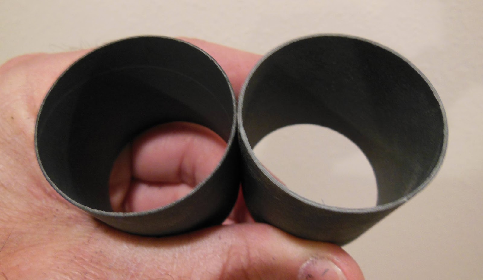
I could have made the ring from a standard black coupler but I didn't have any extras.
A scrap piece of Quest 40mm was a good fit.
A single ring by itself (one body tube wall thickness) didn't seem thick enough.
I'll make a double wall thickness for the mount block ring.
Two rings from the Quest 40mm tube were cut to 3/8" long.

The first (outside) ring is left as is. The inside ring needs a piece cut out of it to glue inside the larger ring.
Slice through the inside ring with sharp scissors. Make the cut as straight as you can.
TIP: For strength, keep cuts like this away from any seams inside or outside the tube. This prevents a badly glued wrap from peeling.

Slip the cut ring inside the larger first ring and mark the overlap. Cut off the overlap just inside the pencil line.
This should give you a ring with a tight fit inside the larger first ring.

Here's how the forward centering ring will sit against the block ring.

The fit against the two engine cluster mount is tight!
I may have to bend and compress the right and left sides of the motor mount tubes so they won't catch on the block ring when inserting this mount.

Fit of this block ring and the mounts is critical! I still haven't glued the interchangeable mounts together until I'm sure all three fit in and lock easily.

Centurion Project Part 3 Baffle

Jumping ahead a bit to the Semroc baffle, included in the Centurion kits:

Be sure to coat the punched plates with white glue.
The left side of the picture shows the amount of glue applied before smoothing it out.
I was amazed how well the flat plates held up to repeated ejections when I did the "autopsy" on my old Centurion. I'm convinced the white glue coats help protect the thick card stock.

Pick up the excess glue out of the punched holes with a Q-Tip.
Two coats of white glue were applied to both sides of the punched disks.


Sand down the angle cut ends of the coupler with 220 grit on a block.
The ring on the left hasn't been sanded.
Enlarge the picture and you can see the sanded ring edge on the right gives a wider gluing edge.


TIP: When gluing the plates on the coupler:
In addition to the glue on the edge, apply a line of glue a little inside the edge of the coupler.

Go to the next picture -


Set the disk on the edge and turn the coupler against the still disk a few times.
Turning the coupler smooths out the glue on the inside edge into a smooth "automatic" fillet.


Even with careful gluing, you will still have to sand the disk edges even with the sides of the coupler.

Be sure to sand the coupler until you get a smooth slide into the body tube. You don't want the coupler to freeze up in the wrong position when glue is applied.

Oops! I forgot to tie on the shock cord!

Saturday, March 30, 2013

Centurion Project Part 2 Engine Mount Parts


Here's the rings and motor mount tubes for the three engine mounts.
From left to right:
Single 18mm, Two engine 18mm and the single 24mm parts.
These two engine cluster rings are available from Semroc.
I used the rotary punch to allow movement of the engine hook.

The left lower ring has a larger recess for the bottom of the hook.
The right upper ring has been slightly punched for the upper end of the hook.

Friday, March 29, 2013

Centurion Project - Part 1 Interchangable Motor Mounts

Before I start the next build, check out this past blog post about Marc Goldstein's interchangeable motor mounts: HERE

I'm using his locking, interchangeable motor mount design on my Semroc Centurion builds to follow.

This is going to be a three model build.
The first "Centurion" was finished earlier, the Estes Cosmic Explorer. It's a BT-55 design based on the older Centuri Centurion.
The second Semroc Centurion will be built stock with an 18mm motor mount.
The third Semroc Centurion will be stock except for the three different motor mounts:
1X - 18mm, 2X - 18mm and 1X - 24mm.

I'll be doing comparisons between the Semroc Centurion and Estes Cosmic Explorer throughout the build.

Wednesday, March 27, 2013

Centering Rings - DIY! Part 3


I always cut more than I'll need and use the best, finished pieces.

It's easier to stack the rings on the tube and sand them at once for a consistent size.
The ring edges were a little fuzzy. These mounts will also be removable.
I decided to harden up the edges with some medium CA glue.
The CA will seal the edges.
On a removable mount, these outside edges won't be glued into the tube. So a hard, smoother edge in this application is a good thing.

CA was applied with a Q-Tip and sanded smooth, still retaining a sliding, friction fit in the ST-16 tube.


Here's a good fit of the ring in the mainframe tube.
Certainly not as clean as a laser cut ring, but probably stronger. The framing mat cut rings are thicker than a typical ring supplied with a kit.

Tuesday, March 26, 2013

Centering Rings - DIY! Part 2

Here's an email tip from Brian Coyle with a better way to center the interior tube circle: 

Here's a tip to help align multiple circles when using tubes like you're doing on the blog (instead of a compass).
Draw cross hairs on the CR material.
Use a 4 fin wrap to mark the tube
Align the tube using the markings
Rinse repeat for the second circle.

Thanks Brian! I have done it this way before with great results. For whatever reason I simply "eyeballed" the interior tube and traced around it this time.


Check the fit on the motor mount tube before sanding smooth the inside diameter.
This is just a small piece of 220 grit to smooth out the rough edge.


Sand a bit, check the fit!
You'll want a friction fit on the inside tube.

I still haven't cut out the outside diameter of the ring.


The outside circle is much easier if you have good, sharp scissors.

Here again I am cutting just inside the pencil line. This line was traced from outside the mainframe tube. Of course, it needs to slide into the tube so it is cut slightly inside the line.

Monday, March 25, 2013

Centering Rings - DIY! Part 1

I need some "non-standard" centering rings for an upcoming build.
A series of three interchangeable engine mounts will be made for a Semroc Centurion.
I don't use BT-20 tubes for 18mm engines, they are too thin and weak. ST-7 tubes will be used.
No BT-50 tubes for the 24mm mount, again too thin. I have some thick walled BT-50 tubing.
The Semroc Centurion uses a Centuri style ST-16 mainframe.
Sure, I could put in a custom order, but sometimes it's quicker and cheaper to just make your own from scrap framing mats.

I don't have a circle cutting compass. I know, I should have one. These rings will be cut with a new #11 X-Acto blade.

Trace around the larger diameter tube first. You won't be able to visually center the large tube if the smaller motor mount tube circle was drawn first.
Use a sharp, thin mechanical pencil.


With the larger tube diameter drawn you can center the inside tube circle inside of it.
Draw and check the center circle. If it's off, erase and redraw.
It might take a few tries.
TIP: Cut the smaller inside circle first!
You'll want to have plenty of border material to hang onto.

Here I'm cutting a little inside the pencil line.
The traced line was drawn around the outside of the tube. You have to make allowances for the thickness of the pencil line next to the outside diameter of the motor mount tube. You can always sand to a perfect friction fit.

Sunday, March 24, 2013

Centurion Project Cosmic Explorer Finished


While I still like the wider girth of the original Centuri (Semroc) Centurion, the Estes Cosmic Explorer looks good.
I don't like the Dymo Letter Maker font name decal and the fins surface seems big for this BT-55 tube.
TTW fins on a LPR rocket? Unnecessary but alignment is easier and laser-cut anything is a good selling point.
The decals are tricky to piece together, plan ahead and be sure you know where each red strip goes.

Be very careful with the red coupler, the dry fit in the BT-55 tube was too tight! Too many have had problems with a red coupler freezing up when being glued in.
The 18" diameter parachute seems a bit big, it'll probably get a spill hole,.

Saturday, March 23, 2013

Centurion Project Part 10 Cosmic Explorer Upper Body Paint Problems

I should be done with this model by now! I had problems with the Rusto 2X Gloss Black.

I did my regular two light coats followed by a heavier "wet" coat.
The final thicker coat crazed and wrinkled!
Who knows why? The weather has been cold one day and warm the next. Maybe I didn't wait long enough for the undercoats to dry.


When sanding down the wrinkled surface, some of the paint layers rolled up!
I continued to sand it as smooth as I could get it.


Three coats of filler / primer followed, sanding between coats.
This raised the lower dips and peeled area.

The upper body and nose cone are ready for the second try of gloss black.

Friday, March 22, 2013

Centurion Project Part 9 Cosmic Explorer Fin Decals


The edges can be trimmed off with a new razor blade.
Use a light touch, just enough to cut the decal film and not into the fin.


The trimmed fin decals leading edge is at the top.

The inset picture shows the trailing edge.
All the decals got a sealing with some Future applied with a Q-Tip.

Dip the Q-Tip into the Future, dab off the excess on a paper towel and apply over the decals concentrating on the edges.
If your finish is good and very glossy, applying Future over the entire model isn't needed. I only apply it over decals that might crack and lift.

When the Future is applied you can see the decal "seat" better on the painted surface. The red color looks richer after the seal coat.

I know - many builders have great results brushing Future over the entire model. That doesn't work well for me.

Thursday, March 21, 2013

Centurion Project Part 8 Cosmic Explorer Fin Decals


The supplied red fin stripes aren't long enough to sit centered on the fins as shown on the face card picture.
Luckily the fins are tapered, the outside edge is shorter than the root edge.
I kept sliding the stripe away from the root edge until it spanned from the leading edge to the trailing edge.
I cut a piece of card stock for a baseline template. By using the template, all the four stripes will be parallel with the root edge and vertical.

I guessed at the height of the template and was wrong.
It reads 1 9/16" away from the root edge but should have been 1 11/16" tall. Still, it helped to align the fin stripes.


Four fin stripes are provided.
I had built a Semroc Centurion a few years ago and thought the red stripes went on both sides of the same two fins.
After looking at the old Centuri instructions I could see one stripe went on each fin. One stripe on each left fin side.

The ends of the stripes are squared and should be trimmed after they have dried. Don't trim them before they dry, they are too flimsy when wet and you'll get a rough edge.

Tuesday, March 19, 2013

Centurion Project Part 7 Cosmic Explorer Decals


The Estes instructions are very vague about the red stripes decals and their placement. The face card barely shows the long red stripe down the lower white body tube.

For a better reference I went back to the 1972 Centuri catalog. Enlarge the picture and you can see the long stripe on the bottom edge.


Here's the decals included in the Cosmic Explorer kit.

Going counterclockwise, starting with the nameplate decal.
(I don't understand the font choice in the nameplate. It looks like an old Dymo Lettermaker strip!)

Immediately below the nameplate decal is a red strip about 4 3/8" long.
This is the horizontal band (below the upper black tube) that goes around the tube.

Beneath that are the long stripes (8 1/2" long) that go vertically down the tube. The long vertical stripes are made with two pieces. The upper pieces (3" long) are on the middle right side of the decal sheet.

The four shortest pieces (2 1/4" long) go on the fins.

Plan ahead before even thinking about soaking the decals!
The nameplate will have to go on the opposite side of the launch lug.
The long vertical stripes go above and blow the nameplate decal centered between two fins.

The longest vertical stripe goes on first from the bottom and up.

Sight down the tube to be sure it is straight and centered between two fins.
With the longest stripe piece (8 1/2" long) even with the end of the body tube it won't be long enough. Piece the 3" long piece on top of that.


This leaves about 1/2" from the top of the white tube piece.
The horizontal stripe (4 3/8" long) caps off the vertical stripes.

The picture at the right is just for reference, the horizontal stripe should overlap the vertical stripes.


With both vertical stripes in place you can better center the nameplate decal.
Center the round compass between the stripes