Showing posts with label Stingray. Show all posts

Wednesday, October 3, 2012

Estes Mk-109 Stingray Build Finished


For a plastic E2X rocket, it looks pretty good! With the fins strakes, it reminds me of the Centuri Nomad model, only shorter.
It should be a good one for flying A6-4 engines in the soccer field.

Things learned:
This group of E2X rockets used only plastic glue for construction.
The plastic engine mount resembles the complex girder style of the larger Q Modeling kits.
TTW fins, TTW launch lugs and an external shock cord mount. It's unsightly, but this mount allows a new shock cord to be easily installed.
I still hate stick on decals. They should be applied over a gloss painted surface, not the flat finish body tube.
This model needed seams filled and the gloss white undercoat.
I forgot how "stringy" plastic glue can be.

Sunday, September 30, 2012

Estes Mk-109 Stingray Build Part 13 Decal


The single checkerboard square got the clear edges trimmed off.


I saved the most difficult fin pieces for last.

Set one in place so you can mark the horizontal (here seen vertically) for measure and marking the other fins.

All the fin root edges were pencil marked at 9/16" from the trailing edge of the fins.

When setting down a large piece like this, try to burnish from the center to the edges. This will keep out any bubbles.


TIP:  All the decal pieces were set in place stuck to the tip of a clean X-Acto blade.
Try to place all the decals using the knife blade and not your fingers.

Don't let your finger prints get on the sticky side of the decals. Any oil on your fingers will show up under the clear surface.

Estes Mk-109 Stingray Build Part 12 Decal Centering

Even the Mk - 109 decals had some of the clear edges trimmed off.

Here I'm finding the center point of the decal to center it between the bands already in place.

You do want to plan ahead. The words NAVY and the MK-109 decals should be centered between the bands. Apply the bands first and then center the word decals.


From the rear you can see a faint pencil mark right above the rear band.

I'll center the dash after the lower case "k" on this line.
The decal isn't burnished down until it is centered and straight.

It's hard to see but there is another faint pencil line above and to the right of the dash, below the root edge of the upper fin.
This is the center mark between the two outside band decals.

The right side of the dash (the decal center) is below this line.

Saturday, September 29, 2012

Estes Mk-109 Stingray Build Part 11 Decal Bands

When using stick on "decals" always apply the easiest ones first to get a feel for the thickness of the plastic and how sticky they are.

Some use water to allow repositioning, I prefer just to stick them down off the sheet.

The rear most band is too wide with the clear edges!
I was right, it is wide enough to cover the rough seam.

Note all the band decals will start and finish in line with one fin.


I returned it to the backing sheet to trim off the clear sides.

Use a sharp knife and straightedge and trim to the black borders.


There is one band above the fins without a black border.

A wrap of masking tape was placed above the red band location to give a straight edge for alignment.
If you can help it, you don't want to lift and re-apply self adhesive decals!

Estes Mk-109 Stingray Build Part 10 Paint Prep


The fin roots had quite a few gaps left from the plastic glue.

After going over the joint with 400 grit, some Titebond Molding and Trim Glue filled the open areas.


The back end had more gaps where the engine mount butted up against the body tube.

Looking ahead, the rear stick on decal wrap should cover this up.

After a light coat of white the entire model was lightly sanded with 400 grit.
A second light coat followed with more sanding.

Here's how the model looked after the heavy applied third coat.
To get a heavy final gloss coat, simply slow down the passes with the spray can.

You want to apply the final coat heavy enough to look wet but not so heavy as to get paint runs.

Friday, September 28, 2012

Estes Mk-109 Stingray Build Part 9 Paint Prep

There isn't much to say about gluing on the fins.
They are TTW and pretty much align by themselves.

Go light with the plastic glue. Any excess will be squeezed out along the root edge line.

The model design looks good, except for the lugs and external shock cord mount. The pictures on the box don't show them.


Before spraying with gloss white, I like to brush down the body  with a soft brush to remove any dust and crud.

Some people like to use tack cloths, but be careful. The sticky coating in the tack cloth can be transferred onto the body surface (especially with a new tack cloth) and may not be compatible with your spray paint.

Estes Mk-109 Stingray Build Part 8 Nose Cone Prep


As with most nose cones, you have to clear the eye of the nose cone.

Notice the direction of the X-Acto blade. The sharp side is facing away from the post.
Using just the tip, punch a small hole and cut away from the "L" shaped post.
Cut halfway along the thin plastic flash.


Reverse the blade and cut toward the cut you just made, finishing the cut line in two halves.

This protects the "leg" of the plastic eyelet.
If you tried to cut it all the way across you could cut into the leg post.
The hole in the shoulder base will have to be larger to get the clay "snake" in the hollow nose cone.

This clay snake weighed .25 oz. That seems typical for a "pat" of clay supplied with the Estes kits.

The instructions say to use a small phillips screwdriver to pack to clay in the nose cone tip. I used a squared off dowel end.

Thursday, September 27, 2012

Estes Mk-109 Stingray Build Part 7 Shock Cord

This model uses an external shock cord cowling to hold the tied cord in place. Even though the cowling looks "aerodynamic" it still sticks out like a sore thumb.

This cowling fits into the upper, larger cut out square.

Notice the tab is deep, much thicker than the tube wall.

 In the Parts Layout drawing, it says the "U" shaped lock piece is not used.

I don't know why it isn't used, the thick tab might hang up a parachute shroud line or shock cord.

The lock piece is tapered so it wedge fits and holds the cowling on tight.
I decided to use it for a stronger hold.


This is a dry fit of the U lock over the inside of the cowling tab.

Even a dry fit (no glue) was very tight and difficult to remove!

I did finally get the two pieces free and both were glued and wedge fit together.

The supplied shock cord was too short so I substituted a much longer piece of elastic.

The elastic shock cord is double knotted and slipped through the cowling slot.

Don't leave much of a "tail" on the shock cord, it could overhang the cowling edge.

Wednesday, September 26, 2012

Estes Mk-109 Stingray Build Part 6 Fin Prep


There is a mold line running around the outside of the fins.
This will show up when paint is applied so you should sand it down and re-round the edges.

Some of the TTW fin tab have rough edges from when the fins were broken off the molding trees.

These should also be sanded off. With that plastic nub on the root edge the fin won't seat all the way into the notch.

Estes Mk-109 Stingray Build Part 5 Mount and Lug Gluing

The body tube seams were filled with CWF and sprayed with grey primer.
This is the tube and nose cone after the grey primer was sanded down.

I tend to spray on the primer a little thick.
The bulk is removed with 220 grit followed by smoothing with 400 grit sandpaper.

 The engine mount was dry fitted to show the TTW launch lug mount locations.

The instructions show the engine mount simply slid in place with no glue. It is held in place by the glued in lugs and fins.

I slid the mount 3/4 the way in and added glue to the inside of the tube edge.
The mount was slid into the glue while the mount was rotated so the lug squares were lined up. (The picture shows the mount dry fitted, not quite all the way in.)

With the mount all the way in, the lugs are glued into the cut squares and into the plastic in the engine mount.

I made a small pool of plastic cement and used a toothpick to apply and spread out the glue in the hole.

The small molded "divot" will face the rear of the model and not be noticed.


The body tube holes were a little larger than the lug tabs.

The lugs were pressed forward so the small open slot would be to the rear and less noticeable.

Monday, September 24, 2012

Estes Mk-109 Stingray Build Part 4 Fin Prep

The engine mount is shown dry fitted into place.
The TTW fin slot is lined up with the engine mount slots.

You can clearly see the wide seam running around the body tube.
The package advertises "No Painting Required!" Yeah right -
A flat finish body tube with glossy self adhesive decal stickers.
How bad is that going to look?

I'll fill the seams and paint the model gloss white before adding the sticker decals.

That's a BT-50 scrap set into the front of the main body tube.
You can see how much smaller it is.

This tube would have to be called a BT-53, it is slightly larger than an Estes BT-52. I had some scrap BT-52 left from the Thor Agena B build.

This is the front end of a fin near the TTW forward slot.

There is a molding "circle" to the right of the tab on the flat surface of the fin.
These circles are easily sanded off with a sanding block with 400 grit.

Two of the three fins had raised circles.


One fin had a recessed molding circle.
This wil be filled with a "pool" of medium CA glue and sanded to surface.

That little pool of glue took 20 minutes to dry before I could sand it down.

Sunday, September 23, 2012

Estes Mk-109 Stingray Build Part 3 Engine Mount


With the centering rings glued and dried, the engine hook is set into the forward notch.
There is just enough room behind the forward tab for the hook front bend to slide in.


 This is the notched engine mount section wet over the engine hook.
It almost snaps down in place over the blue tube.

Down the middle you can see the square recesses for the TTW launch lugs.


Here's piece two of the engine mount section being dry fitted.
I'd recommend dry fitting so you can see where the plastic glue will go.

There is three small notches in the lower ring that fit inside ridges on the engine mount sections.


Rubber bands were wrapped to apply a little pressure while the plastic glue dried.
The long TTW fins slots would dry raised away from the tube without the rubber bands holding them down.

The finished mount reminds me of the complex "wood girder" style mount used in the Q Modeling kits.

Estes Mk-109 Stingray Build Part 2 Engine Mount


Check for any molding tabs or burrs.
I'd never get this ring against the tube if this tab were left on.

Notice how the raised tab fits into the upper notch in the blue tube.
 The instructions are a little vague about where to apply the plastic glue.
Plastic glue is typically messy and will leave long "strings" when you pull the tube away from the applied glue.

The instructions show the glue applied to the ring. If the ring were pressed into the tube, the glue would ooze out around the outside of the ring.
I decided to apply the glue inside the tube edge. With the ring pressed into the tube, the glue stays inside the tube.


Have some Q-tips handy to pick up any excess plastic glue. It'll get everywhere!

Saturday, September 22, 2012

Estes Mk-109 Stingray Build Part 1 Parts

I bought this one from a sale on TRF.
It was a boxed E2X kit available from 1997 - 2003. Catalog number is EST 2131.

I like the looks of it and not knowing how many plastic parts were included, I bought the kit.

The box advertises:
"Unique Ship to Air Missile Styling!"
"Easy to Build, Fun to Fly Over and Over!"
"No Painting Required!" Made in the USA

I usually question a package with too many exclamation marks used in the descriptions.
No painting required? Wait 'till you see the body tube seams!

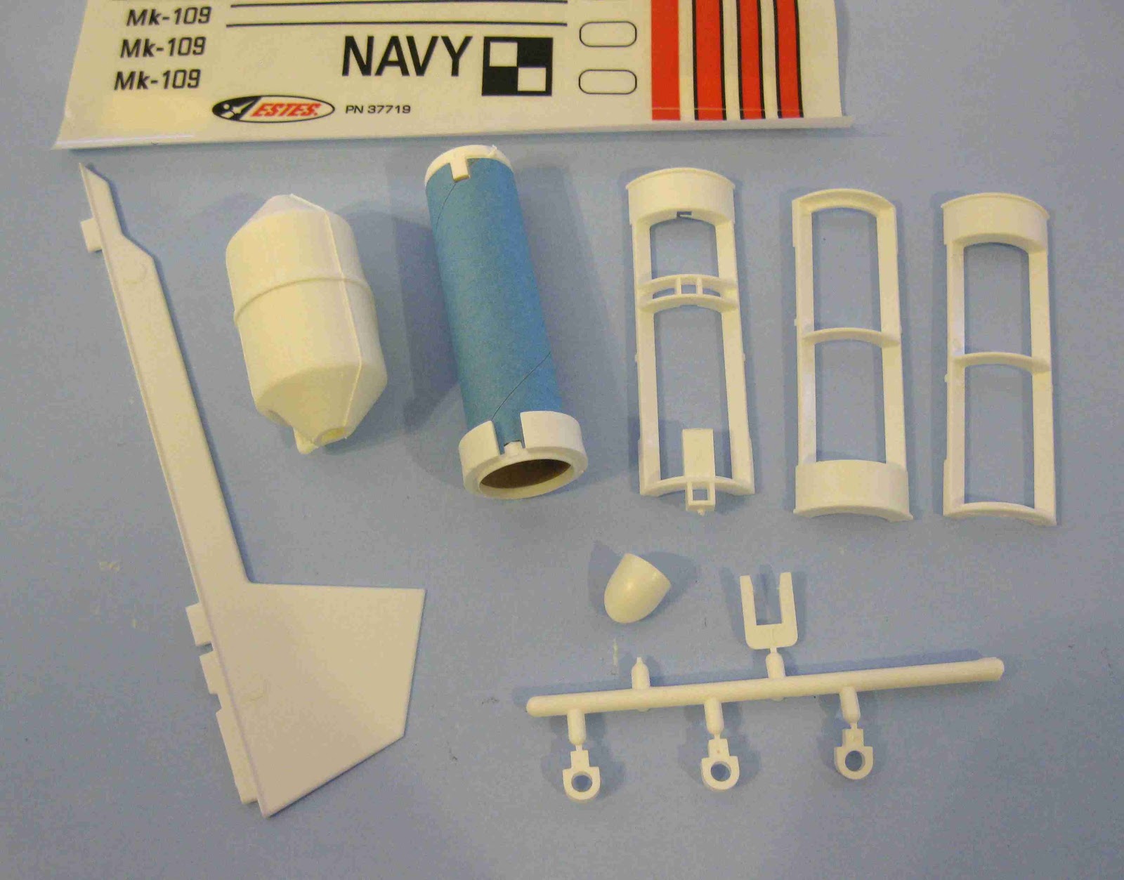
Parts looked clean, the plastic parts were very well molded.
The fins look very thin, under 1/16" thick.

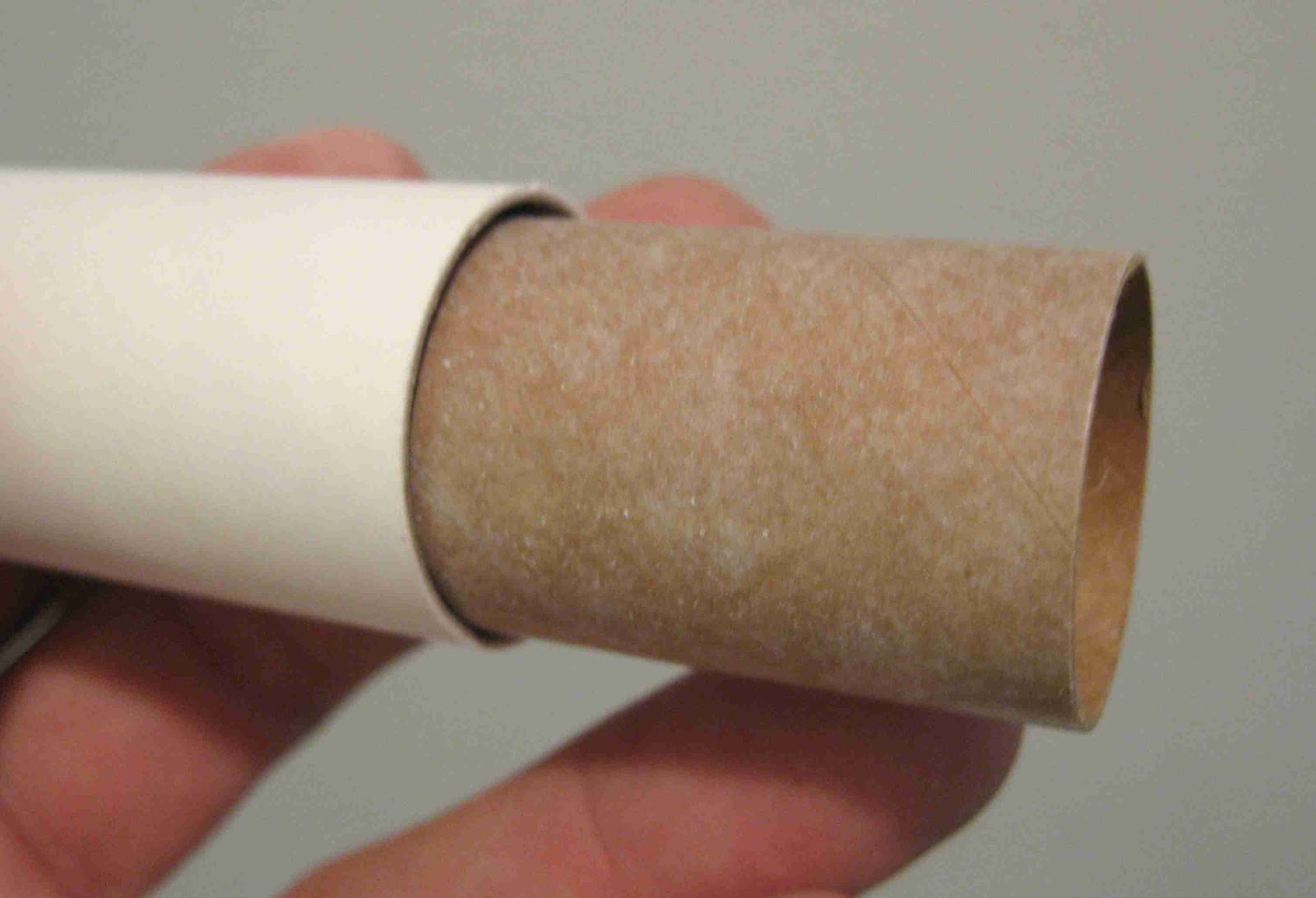
The body tube isn't a BT-50 but slightly larger diameter. I checked it against some BT-52 I had, it's still larger, maybe a BT-53?
The tube walls are thick.
The blue engine mount tube is thicker than other blue tubes I've seen. I usually would swap out a thicker tube, but this one looks stronger than normal.

Fin slots look to be laser cut, (or maybe punch cut) all clean edges.

Some parts of interest:
The self adhesive decals - yuck!
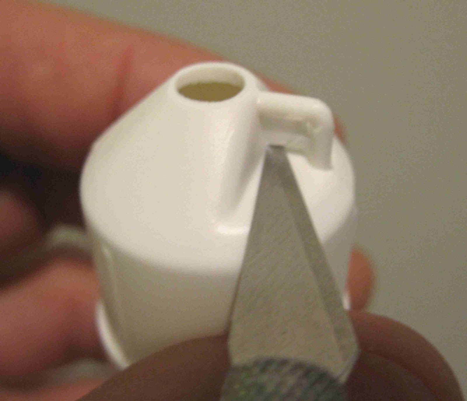
That coupler was molded into the base of the nose cone but isn't used in the kit.
(I'd save it for a future build, but it won't fit any tubes I have.)

The white plastic centering rings (already on the blue engine tube) dry fit very well. The rings lock around notches cut into the blue tube.

The three pieces to the right glue around the centering rings, over the motor tube. They have through the wall fin slots that fit the root edge tabs. One of the pieces has recess squares for the small launch lug pieces.

At the bottom is the plastic tree.
Three small lugs are included, only two are used.
Above the lugs are the external shock cord cowling. The piece to the right of that is meant to be discarded but it locks the shock cord cowl tabs on the inside of the tube.