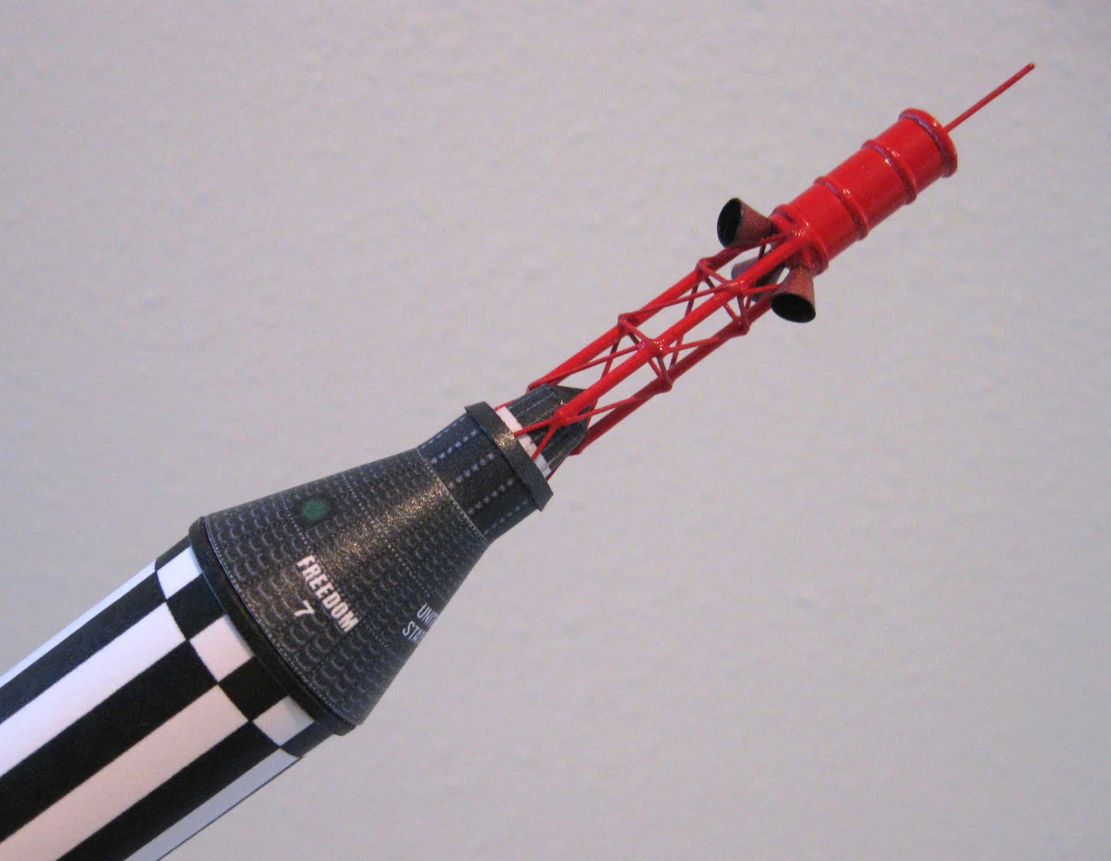
Showing posts with label Freedom 7. Show all posts

Tuesday, May 19, 2015

Dr. Zooch Redstone Pics


I got a question regarding the capsule wrap shroud on the BT-50 based Dr. Zooch Freedom 7 kit. (Picture on the left.)
The picture on the right is the Dr. Zooch Mercury Redstone, BT-60 based kit.
Daniel E. had a concern about the fit of the conical shroud over the balsa capsule.
His shroud didn't fit all the way down to the bottom of the nose cone shoulder lip. The balsa capsule might have been made a little large. It doesn't take much to throw off the fit of the conical shroud.

Here's my response:
Hi Daniel,
I thought about your email today, regarding the fit of the capsule shroud on the Freedom 7 model. Hopefully I got it right! I knew you had said the Freedom 7.
The two Zooch Redstones are different.

The BT-50 Freedom 7:
See the first picture, the shroud does fit all the way down to the bottom and butts up against the body tube when slid into the tube.
There is a ring wrap on the body tube end to simulate the wider, flared base of the Mercury capsule.

BT-60, Mercury Redstone:
Second picture - 
Same thing here except the ring on the end of the body tube is actually a narrow  reversed conical shroud (wide end facing up)
At the capsule base there is a thin red ring wrap.
Both of the built up rings also make up the wider base at the low end of the capsule. 

I hope the build is coming along well!
I'll probably end up building two of the Estes Mercury Redstones down the road.

Thursday, May 19, 2011

Model Profile Dr. Zooch Freedom 7

This is the Dr. Zooch BT-50 version of the Mercury Redstone Freedom 7.

This smaller Redstone is around 13 1/2" tall. Currently, the blog header picture is the capsule and tower of the larger, BT-60 based Zooch Redstone.


This smaller tower has three vertical dowels on the outside. Thin stiff wire is is used for all the cross struts, like on the Saturn 1B tower kits.
The fins are two piece.

As I've mentioned before, these Zooch kits are favorites and a throwback to what rocket modeling was in the late 1960s through 1970s. That is - before ready-to-fly, plastic nose cones and laser cut parts.

Thursday, September 9, 2010

Freedom 7 Build Part 27 FINISHED!

The Dr. Zooch Freedom 7 is finished!


This is another great offering from Dr. Zooch. I always find his kits to be a rewarding challenge.

This BT-50 based Mercury Redstone is the same scale and about an inch taller than the Zooch Jupiter C. My Jupiter C has flown on a B6-4 and it really screamed! I'll expect nothing less from this model.

Freedom7 Build Post 26 Launch Lugs


The launch lug had to be filled, painted and cut in two before gluing onto the body wrap.

Here it's been filled with CWF and sanded to surface.

It was then sprayed with gray filler, sanded smooth and sprayed white.

After it was cut in two, it was ready to be glued in-line on the body tube.


The two lugs were lined up using a short length of launch rod. I let the legs rest against the rod while the glue dried.

Before taping the rod to the body tube wrap, I made the tape a little less tacky as explained in an earlier post. I didn't want to take any chance of pulling up any of the wrap printing.

Wednesday, September 8, 2010

Freedom 7 Build Post 25 Fins


The instructions don't mention doing this but I wanted a stonger glue joint than just a surface mount for the fins.
Certainly nothing new, these are Glue Rivots.

Holes are punched along the fin placement line. When the glued root edge is set onto the body tube, glue will sink into the holes making glue rivots.

Be sure not to punch too deep, just through the outside tube. Keep the needle holes right on the fin alignment lines.


With all the fins in place, the Freedom 7 is nearly complete.

Freedom 7 Build Part 24 Fins


Here's the four finished fins after removing the tape.


Be sure to sand off any paint on the root edge before gluing to the body wrap. This will be a surface mount so the joint should be strong.


The engine mount is glued in.
Be sure to center the engine hook between two fin locations.

Freedom 7 Build Post 23 Fins


The Mercury Redstone fin mask can be confusing.

I set the fins against the printed body wrap for masking, being sure the rear under hang was against the lip of the body tube. Scotch tape was used for the black / white separations. The clear tape was set in place while the fin was on the body tube to make sure the fin color separations would match the body tube print. Lay Scotch tape down at the color separation line. All other areas (not painted black) are covered with masking tape and pieces of a plastic grocery bag.

Before laying down masking tape, sometimes I'll reduce it's tackiness by sticking the tape on my pant leg. When the tape is removed, some lint and small threads from the denim is left on the adhesive side so it's not as sticky.

This is not done on the clear tape I use for color separations. You want that tape to seal the line between the colors.

In preparation for the black spray, the fins were set flat on their sides. One side of the fin will be sprayed first. The tape is removed, the fin turned over and then re-masked for the black pattern other side.

This picture shows the fins ready for the first black spraying. The black dots on the Scotch tape are simply black spray reference marks.

Freedom 7 Build Part 23 Fins


The steering vanes were glued to the outside edge of the main fin.

I used one glued fin and vane as the master. When gluing the vanes to the other fins I held them side by side to make sure the vanes were raised to the same height.


All the fins were set down on a smooth surface for drying, making sure the vanes were flat and even with the main fin surfaces.


Tape was set down sticky side up on an old cutting cardboard to hold the fins vertical for the gray primer coats. Set the fins far enough apart to allow easy spray coverage.

The fins are masked and painted off the model. Notice the back end of the fin hanging over the back of the board.

Tuesday, September 7, 2010

Freedom 7 Build Part 22 Fins


I tried to save some time by gang sanding the steering vanes pieces.
All were taped side by side and the taper marked with a pencil.

I couldn't sand them like this, they moved around too much. I ended up removing the tape and sanding separately.


Following the same sanding directions from the last post, here's a finished steering vane ready for filling.

And, the four main fins.

After applying filler, sanding with 400 grit sandpaper will sharpen the leading edge "wedge" even more. Just take it slow, always take a moment and "set" the block flat on the taper before sanding.

Freedom 7 Build Part 21 Fins


The fins are cut out using templates from the wrap sheet.

I didn't use the supplied kit balsa, it seemed soft and wouldn't hold the sharp tapered, leading edge.
I cut the fins from some harder 1/16" balsa. Double check the grain direction on the steering vane pieces.
Here I'm checking the 90 degree corner angles of the fins using a 2" machine square. You can see the fins are pinned together for uniform sanding.


People have asked how I get a defined sanded edge on fins. I'll do my best to explain.

The taper is marked on the fins with pencil.


You must use a sanding block. The sandpaper grit is chosen based on the density of the balsa. This is a harder balsa so 220 grit was used for the initial shaping.

Don't just sand back and forth and expect good results.

Set your block on the edge and visualize the angle of the taper. Change the angle of the block to match the final angle. Sand only on that angle "plane". Go straight - back and forth, don't rock the sanding block.

Make just a couple of passes and check your work under a strong light. Be sure what has been sanded is the same depth and consistent on both sides. If not, adjust pressure on your block to take a little off the high side.

Now that some of the taper has been taken off, set your block back on the fin. Set the block flat on the area already sanded matching the angle of the block "attack". Make a few more passes, each time being sure the block is sitting squarely on the area already sanded off.

A quick review:

  1. Mark the edge with a pencil reference line.
  2. Always use a sanding block
  3. Set the block on the leading edge, angle the block to the desired angle
  4. Make a few passes then check your work under a strong light. Adjust the angle of the block to correct the sanded angle
  5. Before making sanding passes, always set the block on the sanded taper making sure it sits flat on the already worked area. Make a few more passes, check it again under the light

I don't sand the leading edges to a knife edge. On the finished fin there is a narrow, squared off leading edge. If you can see light through the balsa you've sanded down too much.

Monday, September 6, 2010

Freedom 7 Build Part 20 Body Wraps


I don't do my body wraps as directed in the instructions.

I've tried to use white glue on the outside edges then wrap around the body tube, but when the edges should match up it's never close enough for me. Using white glue you only get one shot at wrapping it correctly.

To make it even easier, I cut the wrap in two right under the black band between UNITED and STATES.

I spray the underside of the wrap with spray adhesive, line it up with the pencil line and wrap. The spray adhesive gives you a second or even third try to get it straight.

Here's the bottom wrap (STATES lower half) lined up with the bottom of the body tube.
The upper UNITED half was lined up with the top of the lower STATES wrap and rolled in place. Once the two wraps are "butted" together, you'll never see the cut line between them.
When using spray adhesive, the end edges of the wrap will lift. You'll have to go back and push a little white glue under the lifted areas and burnish it down.


The instructions have you start the entire wrap against the top of the body tube, but that doesn't give room for the thin upper tank band.

The upper tank band was glued onto the body tube above the upper wrap on what open body tube was left. There was a little bit of body tube to be trimmed and sanded square afterwards.


Freedom 7 Build Part 19 Engine Mount


I'm doing the posts in the same order as the instructions, were now up to page 6.
The engine mount is pretty straight forward, I won't spend much time on this. I'd rather concentrate on the capsule, tower, fins and paint.

This is the rear centering ring. Notches were made for the engine hook with a #11 blade. The center section was removed with a small, square diamond file. Using a flat file gives the notch a cleaner, flatter bottom than I could get with a knife.


Here's the finished mount.

TIP:
Dr. Zooch has solved the problem of the engine mount tube tearing at ejection.
Sometimes ejection charges are so strong it kicks the engine back hard against the rear of the hook. The front end of the hook can tear back through a BT-20 tube.

Just forward of the tape wrap is a reinforcement band cut from the cardstock wrap sheet. (It's hard to see in the picture.) This wrap is glued immediately behind the engine hook notch. A drop of CA is applied to the wrap below the engine hook slit.
The combination of the wrap and hard CA glue probably doubles the strength of the BT-20 tube.

Sunday, September 5, 2010

Freedom 7 Build Part 18 Tower


This cut is a little tricky.
You want the nozzle tab seam out of sight, facing the inside of the tower.

Before cutting the tip off at the correct angle, do some dry fitting against the bottom of the LES canister module dowel. Trust me - double check before doing any cutting.
In the picture, the tab seam is facing my thumb.
The diagonal wire supports seem like they might be in the way.
I did scrape away some paint where the cut tip of the nozzle would be glued.


And finally -
THE FINISHED TOWER!
Whew!
Coming up - the engine mount, body wrap and fins.

I know, the body wrap isn't until page 7, we just finished up page 5. I jump around sometimes. It'll be covered soon enough.

Freedom 7 Build Part 17 Tower


Here's that rotary punch again!
It's the only way I could cut those small circles in the tops of the LES motor bell shrouds.


This time to form the shrouds, I used a smaller sharpened dowel.
You'll just have to try this method to see how well it works. These engine bells are tiny! I haven't found a better way to roll and curve them.


After gluing and drying-

The tip of the same dowel was sanded to a less sharper angle for shroud rounding. Set the nozzle over the dowel, press the nozzle against it's sides and turn on the dowel. Don't press too hard, you could split it open at the glue tab.


This shows the difference between a dowel formed nozzle on the left, and a unformed nozzle on the right.

Freedom 7 Build Part 16 Tower


I probably should have done this before the tower was glued onto the capsule, but I was stuck.
Dr. Zooch has you simply glue the aero-spike toothpick to the top of the LES Canister Module.
I wanted to inset it in the top rather than just do a surface gluing.

The toothpick did look a little thick. While the instructions say you can substitute 1/2" of the wire, I didn't have enough wire left. I cut the head off a pin and cleaned up the rough edge with some small files.

The center was marked and the drill hole was started with an awl. The pin vise drill was used to make a hole about 1/4" in. The pin was painted red and glued into the hole.

At yesterday's launch, I finally flew my Dr. Zooch Little Joe. When building, I had set a pin into the LES Canister Module at the top of that tower. A toothpick spike was drilled and set down on the pin. When it came down on a gravel road the spike was slightly bent, but still held in place on the inset pin. I simply bent the spike and pin back to a straight position - no replacement was needed.


Here I'm forming the clamp ring fairing on the palm of my left hand. I wanted to get it close to perfectly round before gluing in place.


The aero-spike and clamp ring fairing in place.

Saturday, September 4, 2010

Freedom 7 Build Part 15 Tower


The lower inverted "V" support are cut and glued in place.

At this point you realized how little of the red wire is left!
I did have enough. But if I had made mistakes in cutting the upper struts I'd be out of luck now.

In Part 12 of the build I mentioned gluing the tripod tower legs higher up on the antenna fairing than the instruction drawings showed. I wanted the inverted Vs to be taller, more like the real Mercury Redstone tower.

Freedom 7 Build Part 14 Tower


The diagonal braces follow the same method.
Carefully measure and cut the wire.
A little glue is set in the corners.


Tweezers are used to set the wire into the glue drops. When the glue starts to set up and get tacky, you can move the wire into it's final positions.


At this point, the hardest work is done!

Freedom 7 Build Part 13 Tower

The best advice I can give you when making a tower is to take it slow. Double check before you make the wire cuts and be sure all is straight before moving to the next brace.

If you haven't already done so, the small balsa triangle is removed from the inside of the three legs.
Pencil marks are drawn on the legs for the cross brace locations.

I cut the wire so the ends would sit at the center of the legs. Fingernail clippers actually work very well to cut the wire. Be sure to cut accurately, you won't have much wire left when you are through.


Here I've dipped a toothpick tip into a drop of white glue and applied a bit to the pencil locations.


Tweezers were used to place the wire into the small glue drops. When setting in the second and third wires, be sure they are straight and in line with the previous glued wire.


After using white glue on the support joints, follow up with CA applied with a toothpick tip.
White glue is applied again to all the joints.

All three sides have the horizontal braces in place and are ready for the diagonal cross brace wires.

Friday, September 3, 2010

Freedom 7 Build Part 12 Tower


The second paragraph on page four looks to be left over from the prototype model instructions. Just disregard that step.

I punched three small pinholes in a piece of cardboard to hold the wires for spray painting.


Scrape off the paint on the inside of the tower leg for better adhesion. You can see it on the middle leg.


The tower legs are glued onto the antenna fairing.

I looked up a few vendor websites that had pictures of the finished Freedom 7. Both sites had the tower legs glued too far down the sides of the antenna fairing shroud. When the inverted V supports are added, they looked "squashed".

I glued the tower legs higher up to make the final V supports taller.

I'm continuing with the Method "A" tower - making all the remaining tower pieces from the wire. Or, you can go to Method "B" and use the supplied card stock wrap to simulate the smaller tower details.