Showing posts with label Q X-15. Show all posts

Saturday, April 19, 2014

Quest X-15 Finished


Quest did a good job capturing the feel of the X-15.
Even with the longer body tube its a good looking sport scale model.
Adding .25 oz. of nose weight it should be stable even with a C6-5 engine.
I've had this one on my build list for a while.
For now Quest has X-15 parts packs available, the decals were the hardest to find.
The gloss black paint sure shows fingerprints!

The Quest face card states the finished model weighs 1.69 oz.
My finished model weighs 2.45 oz. I did add .25 oz. of clay to the nose, the body tube is 2" longer and there is a card stock wrap inside the end of the body tube for a better fit of the nose cone. I tend to lay on the filler and paint heavier than most.
Unless it's a RTF, most finished models always seem to weigh more than the face card or catalog pages say.

EDIT: The Quest X-15 (stretched and with clay weight as shown) has flown twice now with a Estes B6-4 and C6-5. Both great, stable flights.

Quest X-15 Build, Before Part 8, Fin Gluing - Warning!

From a question on TRF:
Originally Posted by Bill
I bought this kit soon after it came out. There was discussion about a problem with the fin marking template or something. Anybody remember any details?
Bill
My response:
I remember reading something about this.
When I did the blog build, I didn't use the kit marking guide.
I just made one out of folded paper.
I just tried the kit marking guide to see what was in question.

It fits the tube circumference very well, but -
If you look at the picture, the fin guide is actually split into five fin positions.
Four are marked with arrows, the fifth position would be where the edges of the marking guide meet.

The two rudder fins and two strakes should be glued at a standard 90 degree cruciform.
If you marked the tube with the kit guide the fins would be off.

So - 
Don't use the fin marking guide supplied with the X-15 kit or the X-15 parts pack!

Friday, April 18, 2014

Quest X-15 Build, Part 13, Decals


The NASA decal wouldn't reach all the way across the top of the rudder. All the online pictures show the NASA decal set down from the top edge.
Instead of centering the decal I pushed it towards the leading edge.


There are many small decals to place on the model.
Hold onto them with tweezers while soaking, then set on a paper towel until needed. You can soak two decals at the same time.

Even after looking at dozens of online pictures I still couldn't figure out where some of the smallest decals went.
Two of the six "Beware of Blast" decals go at the rear of the tube. Two others go in front of the "X-15" at the nose cone tip.
Two "Beware of Blast" decals were left over.

EDIT: I've seen now where the two remaining "Beware of Blast" decals go on the outside leading edge of the wings. Why a Beware of Blast warning is on the wings or nose cone tip is beyond me. At the rear nozzle end yes. But a blast warning on the nose cone?


Compared to the rest of the model, the nose cone is very busy.
These two views should help with placement.

The #66671 X-15 didn't have the "X-15" on the nose.
I put it on anyway.

Quest X-15 Build, Part 12, Decals


The instructions say to use the face card for the decal placement.
I did some image searches and found THIS.
I don't know if it is accurate or not, it's just another reference.

The #66671 X-15 (kit decal number) is at the lower right.
Maybe the nose cone tip should have been painted silver or white.


Here's more nose detail from another online image.
Sorry, the link I had is no longer working.
Right click the image and then hit "Open image in a new tab" to see an enlargement.


A piece of card stock was cut at an angle for a baseline guide for the USAF wing decals.
The same card stock piece was flipped over for the stars and bars.

Thursday, April 17, 2014

Quest X-15 Build, Part 11, Black Paint


Here's the back end after wet sanding the first light coat of gloss black.

The fillet areas were sanded smooth with 400 grit wrapped around a Q-tip. Sanded to surface, the black paint fills any remaining dips in the fillets.


I don't know what happened here. Even with the nose cone painted with light coats it still wrinkled up when it dried, just on the right side of the canopy.


This was wet sanded and re-shot.


The whole model is shot with gloss black, no masking and no other colors.
Finally - ready for the decals.

Wednesday, April 16, 2014

Quest X-15 Build, Part 10, Lug and Fillets


I didn't bother trying to get a fillet between the bottom root edge of the strake and root edge of the rear fins. It's just too tight an area to apply glue or smooth it out.


From the back, be sure any open areas get some fill at the root edge joints.


The lug is glued to one side of the lower rudder and to the front of the leading edge.
Looking at it now I should have cut the lug front at an angle to match the leading edge.
There are a LOT of edges to fillet with Titebond M&TG.


The first undercoats of white followed.
Shoot the white first directly into the deep angles to be sure you've got good coverage.

Tuesday, April 15, 2014

Quest X-15 Build, Part 9, Fin and Wing Gluing


The back of the wings are glued 2 1/2" from the rear of the tube.
The primer area was sanded off for better gluing surface.


Glue the wings under the strakes.
It won't feel right, but the wings and tail fins both go under the strakes.


The balsa fin guide helps to get the tail fins at the correct angle.
The rounded base won't rest against the body tube, it sits above it.


From the rear it reminds me of a Shrox design, certainly not a conventional fin placement.

The tail fin edge angle is needed for a strong root edge bond.


With the nose cone in place it's an impressive design.
The longer body tube doesn't really bother me too much. It's worth it for better stability.

This is more of a "profile" semi scale model.

Monday, April 14, 2014

Quest X-15 Build, Part 8, Fin Gluing and Root Edge Angle


The top and bottom rudders and two long strakes are glued on like a four finned models, spaced at 90 degrees.
The top and bottom rudders are glued 1/8" from the rear edge of the tube.
The long strakes take a little time, sight from the back and be sure they are straight.


The root edges of the wings and "tails" are sanded at an angle for a better fit against the body tube.

I drew the angles larger on a piece of card stock for easier reference.


It's easy to get the sanded angles mixed up.
I marked the edges with pencil to be sure the angles were "mirror" sanded.


Set the wing and tails on a vertical line and the sanding block at the desired angle.
I didn't sand the root edges while sitting on the drawn lines, but used it for a reference and a more accurate angle sand.

Sunday, April 13, 2014

Quest X-15 Build, Part 7, Engine Mount Gluing

The surface of the Quest centering rings were pretty rough.
I gave them a coat of medium CA keeping it away from the edges where the glue fillet will go after it's set in the rear of the body tube.

Some 400 grit was wrapped around the end of another Q-tip and the hardened CA surface sanded smooth.


Instead of just applying a glue ring in the main air frame tube with your finger, a rounded dowel was marked at the end of the engine tube.
The instructions direct you to glue the mount in with 1/4" of the motor mount tube extended out the back.
I decided to glue the tube ends flush. Even with the mount only 1/4" forward it could move the center of gravity and improve stability.


I had thought the extended motor tube was to simulate the back end profile of the real X-15. All the online images show the back end to be flat.
The kit fins are glued 1/8" from the rear of the tube.


A ring of glue set in place with the marked dowel.
The mount was slid in place and almost to it's final position.
TIP: Before the mount end was even with the outside tube, the mount was turned. Turning the mount smooths out the glue ring at the upper centering ring making an even internal fillet.
I know - no one will ever see it.
You have to work quickly, you don't want the mount to lock-up in the wrong place.


Immediately press the mount even with the 35mm main air frame tube.
I use the flat side of my sanding block to press it into place.
Using a flat block I know the motor mount tube is even with the outside body tube.

Before gluing the rudders and wings in Step 8 -
Check out the late edit post - HERE

Saturday, April 12, 2014

Quest X-15 Build, Part 6, Balsa Filling and Tube Quality


After the balsa was filled with CWF off the model,
The CWF was sanded smooth with 400 grit.

TIP: After sanding down the CWF all the corner edges were very lightly run over with 400 grit. I'm not trying to round off the squared edges, just "kissing off" any roughness on the corners.
I had an older Quest X-15 kit in the build pile. This kit was bagged up in China.
Look at the body tube finish on the face card model. The tube is lumpy with apparent seams.
The Chinese made tube is pretty bad. There are wide seams and it doesn't appear to have a final thin glassiene wrap.
The tubes I ordered directly from Quest in Utah are the better quality you'd see directly from Euclid. The rough tube was replaced with some extras from the spare parts box.

Friday, April 11, 2014

Quest X-15 Build, Part 5, Loose Nose Cone Fix

The X-15 nose cone was very loose in the 35mm tube.
In a smaller diameter tube I would just add a few wraps of masking tape around the nose cone shoulder.
This larger tube will get a card stock shim in the top end of the body tube. This thin shim won't block the ejection of the parachute.
A piece of 67 lb. card stock was cut to around 1" high X 4 1/8" wide.
I came across the width after a few dry test fits.

A glue stick was used on one side of the card stock piece.
This was pressed into the body tube, rolled flat in place with a dowel.

A little of the card stock extended beyond the top lip of the tube.

After the glue stick dried, some medium CA glue was applied around the top end to harden the card stock for easier sanding.
The extended wrap was sanded even with the tube with 400 grit on a block.

The inset picture shows the fit I was looking for.
The nose cone won't fall out of the tube under its own weight.

EDIT: April 13, 2014 -
I've flown the X-15 twice now. It's the Spring and Florida humidity is really kicking in.
This interior card stock shim seems to swell in the damp air and the nose cone felt tight at yesterdays launch.
Humidity can make body tubes swell a little anyway, but this card stock shim really seemed to draw in the moisture.
I'd recommend a light seal of CA glue then sand and polish the hardened card stock with 400 grit.
The picture above shows just the lip of the card stock getting the CA coat. Extend the glue coat down inside the entire length of the card stock.

Thursday, April 10, 2014

Quest X-15 Build, Part 4, Nose Cone Weight

The seam on the blow molded nose cone was pretty clean. There was a slight raised ridge near the tip.
Sanding with 220 grit got rid of most of it. The pencil marks shown in the inset picture are the hollows to be filled.
Medium CA glue drops were set into the low areas.
220 grit took them down, 400 grit smoothed it out.

I'll be adding some clay nose weight inside the hollow nose cone.
To make an access hole, the end of the nose shoulder was sanded down thinning out the tapered end.
Stop sanding before you reach the top of the attachment lug.

This thin plastic was knocked out with the tip of a hobby knife.


The hole was fairly round.
400 grit was wrapped around a dowel to make it more circular.

.25 oz. of clay was weighed.

The clay was broken up and rounded into little pea sized balls.
Drop in one clay ball and press it in with the square end of a dowel.
Drop and press the clay balls in place on by one.
TIP: Small clay balls are easier to press in place instead of chasing around the end of a clay "worm".

Wednesday, April 9, 2014

Quest X-15 Build, Part 3, Kevlar in the Engine Mount

This mount will get the replaceable Kevlar punches.
To be sure the Kevlar tube is directly opposite the engine hook, a pencil "X" was drawn on my work area.
The disk was centered and two pencil marks made at the top an bottom of both rings.

Using the rotary punch the appropriate holes were made for the hook and Kevlar slide tube.
In the inset picture is the upper an lower ring. The smaller holes on the left side is for the Kevlar Q-tip tube. The holes on the right are for the engine hook.

Dry fit the rings to be sure the hook and Q-tip tube are straight before applying any glue.
I also wrapped the electrical tape over the hook and tube before the rings were glued on. With the rings in place you can better center the electrical tape wrap.

I start the tape wrap a quarter turn before the hook. The tape goes all the way around and over the hook twice. It end finishes directly opposite the start of the tape wrap.
This makes a 1 1/2 wrap of tape around the tube. The tape passes over the hook twice.


Here's the finished mount, the top view is on the right.

Notice the Q-tip tube doesn't extend too high up the top end of the motor mount tube. This keeps the plastic away from the hot ejection charge. I haven't had any problem with the tube end melting if it is recessed down from the top end.

Tuesday, April 8, 2014

Quest X-15 Build, Part 2, Centering Ring Laminations


When I ordered the X-15 parts pack, I also ordered four of the Quest 35mm centering rings Part # 16002.

These are cut from thin, rough cardboard. They are probably strong enough by themselves, but seem thinner than what I'm used to.

Two rings were glued and laminated together.
I slid them over a BT-20 sized tube to be sure they were centered.

Clothes pins clamped the two rings together while the glue dried.


Here's the finished rings after gluing them together.
These doubled up rings feel much stronger without adding much weight at all.

Quest X-15 Build, Part 1 Parts


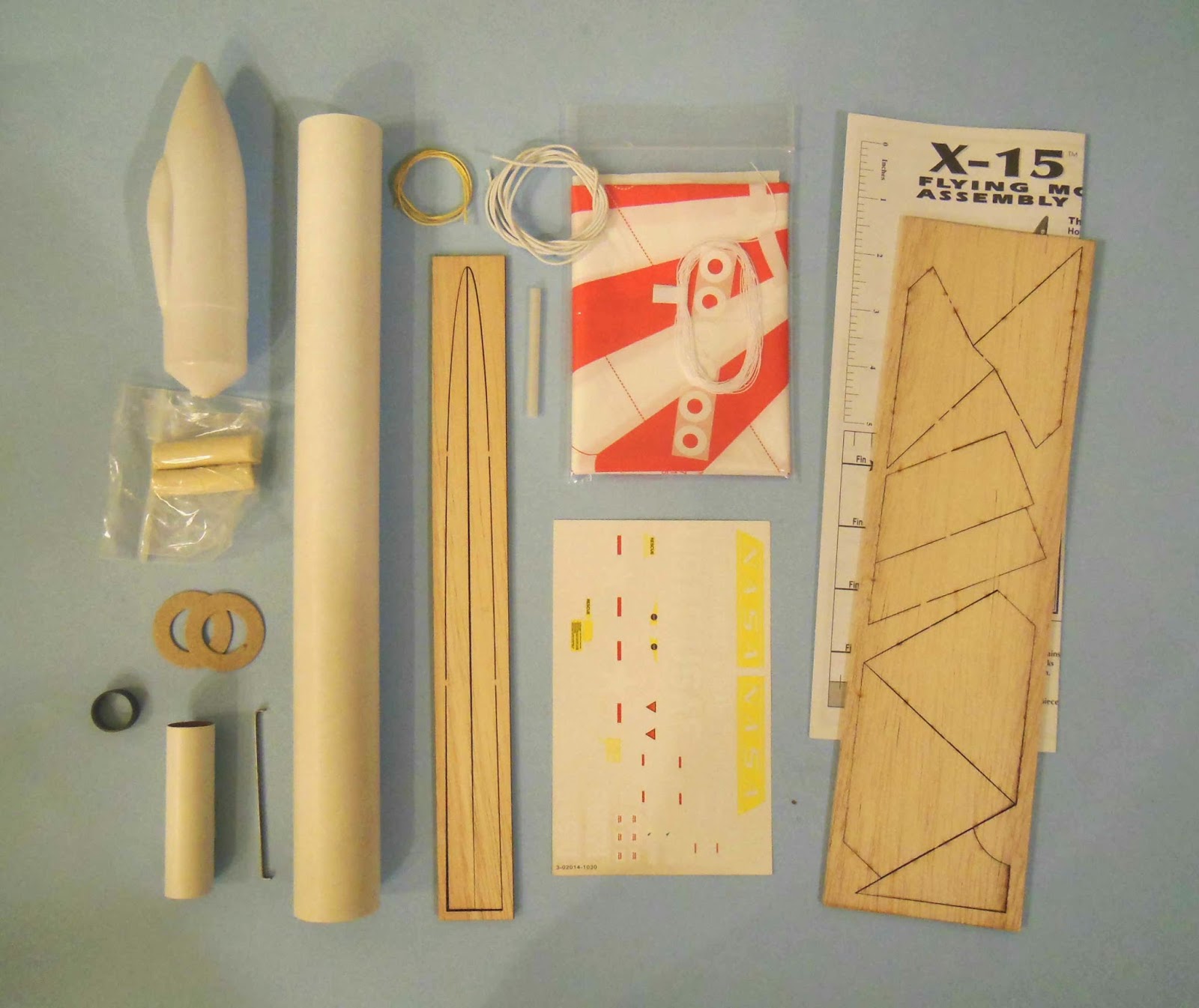
Quest Aerospace is offering an X-15 kit parts pack
HERE


X-15 Parts Pack includes the following parts: 
2014-1010 X-15 Instructions 
2014-1030 X-15 Decal 
20222 X-15 Nose Cone 
33030 X-15 Balsa Big Sheet 
33051 X-15 Balsa Strakes 


Right now the complete kit is OOP.
The parts pack listed above is whats available from Quest.

To the right are all the parts needed for the complete build:

To build the complete model you'll need to add these parts not included in the parts pack:
12" or 15" Parachute
2" Launch Lug
135 lb. Kevlar
Elastic shock Cord
Engine Hook
BT-20/35mm Centering Rings
.25 oz. Clay Weight
Engine Block
Motor Mount Tube
35mm Quest tube, 11" or 13"

Some had unstable flights with the original model. Later, Quest lengthened the 35mm body tube from 11" to 13". A clay weight was also added to the kit.
The X-15 has gone over some recommended engine changes.
Toward the end of the kit run, the A6-4 was the only recommended engine.
On this build I'll play it safe and use the 13" longer 35mm tube and add .25 oz. of clay in the nose cone.
I may not get stellar altitudes, but it should be stable!

Tuesday, March 11, 2014

Small Parts Orders


I got my Quest X-15 parts packs yesterday.
The body tube and centering rings were not in the parts pack, you'll need those Quest parts to make the model. An ST-7 engine mount tube fits the Quest 20/35 centering rings very well. 

All X-15 parts, centering rings and body tube are good quality.


The packaging did surprise me though.
Everything was boxed in a starter kit "cardboard range box".

To the left of the Aerotech/Quest return address were some interesting Chinese (?) symbols. I don't know what the heck that means. The package did come from Utah.


And sadly - 
My last order from Semroc!
This was delivered five minutes before I saw the posting about Semorc closing up on YORF.
This was just a small parts order.
After I got confirmation the order was filled, I got a email from Cheryl telling me Semroc was no longer filling order for vendors. Understandably, I had a feeling they might be bowing out of the rocketry business.
Many thanks Semroc, great people and a great company.