Thursday, December 30, 2010

Cyclone Build Part 12 Fin Gluing


While the instructions don't say to do so, I rounded the leading and trailing edges of the fins before gluing them onto the lower body tube.


The two lower stabilizer fins are spaced at 18mm apart.

I drew 18mm tick marks on a paper wrap and marked the center at 9mm.
The 9mm mark was centered over the engine hook.

Extend the fin lines down the smaller tube.


TIP: Getting the longer stabilizer fins to glue in place is tough! Be ready for a little frustration. They are long and heavier than the wet glue will hold.
You will probably have the best luck using the "double glue" method.

Wednesday, December 29, 2010

Cyclone Build Part 11 Engine Mount


This is from a little farther along the build. I didn't get a picture of the engine mount glued in the lower, shorter BT-20 tube. At this point in construction I haven't glued the stabilizer fins on yet.

The engine mount is glued in the shorter BT-20 so the longer adapter sticks out of the top by 3/4".

This adapter extension acts as a coupler holding the two halves of the rocket together. Don't glue this to the upper body!

Cyclone Build Part 10 Engine Mount


A 1/8" wide slit is cut in the BT-5 for the engine hook, 3/16" from one end.

The engine block is glued in place and rests against the upper bend of the hook.

The shorter 5/20 ring is notched to slide over the engine hook.


The shorter notched ring is slid over the engine mount tube until it is 3/4" from the open end. (on the right of the picture)

The longer 5/20 ring is notched to slide over the engine hook from the front. I drew pencil line around the notch I made to better show how it was cut.


The longer 5/20 ring is glued in place so there is 5/32" between the two rings.

Tuesday, December 28, 2010

Cyclone Build Part 9 Engine Mount Prepping

Right now I'm on a cruise ship going down the Mexican Riviera. Internet connections are slow on board the ship, so only one posting. On the days when the connections are good, I'll do my regular two postings, but this morning - just this one!


The instructions tell you to use the Estes Mini-Engine Mount Kit # 303157.

I think the engine mount kit is out of production, so I made mine from engine casings and some leftover BT-5 tubing.

The 1" long AR-520 was cut from an engine spacing casing. I did have to remove some of the interior winds to get a good fit over the BT-5.


This is the 1" long AR-520 adapter after fitting.

Monday, December 27, 2010

Cyclone Build Part 8 Launch Lug and Nose Cone


The launch lug is glued beside the spar, even with the end of the body tube.


To protect the base of the nose cone from the ejection charge, I coated the base with white glue and let it dry.

The nose cone was then glued in the front of the BT-20.


The upper spin unit is complete. Next up, the lower stabilizer unit.

Cyclone Build Part 7 Main Fin and Dowel Weight


The main fin is glued between the spars.


Clothes pins were used again to clamp the fin in place while the glue dried.


The dowel is glued on the trailing edge.
The tapered end overlaps the fin spar.

Sunday, December 26, 2010

Cyclone Build Part 6 Spar Contour


The instructions specify a 15 degree angle of the spar. This is critical!
You can have a variance of + or - 1 degree.

If the angle is much wider the the upper unit won't rotate.
If the angle is narrower, the engine exhaust will scorch the fin.


The picture shows the spar assembly glued in place. I glued the spar assembly opposite the vent hole. You can see the slot for the main spin unit fin.

Look down the tube from the front and be sure the fin spar assembly is in alignment.

Cyclone Build Part 5 Spar Contour


When sandwiched together, the spar is 3/16" thick.

While it could have been glued to the body tube as is, I wanted a better root edge fit on the BT-20.

I wrapped 220 grit sandpaper around a BT-5 tube and sanded the body tube curve into the wide root edge.

TIP: Notice I didn't sand around a BT-20. You'll get a tighter contour fit by sanding over a smaller diameter tube. The BT-5 is the next smallest diameter.


Here's the curvature of the root edge back on the BT-20 upper tube.

Saturday, December 25, 2010

Cyclone Build Part 4 Fin Spar


The fin spar spacer is glued between the two long fin spars.

I cut mine a little oversize so I could sand it down to the outside edges once all three parts had dried. I made sure that the inside spacer's 90 degree edge sat in the right position as the original, slightly smaller spacer.


I clamped the three pieces together with clothes pins for drying.

With the spacer between the two spars, there is a long open "slot" for the upper main fin.

Cyclone Build Part 3 Vent Hole Punch


First up, you are to punch a hole in the longer BT-20 for an ejection charge vent. This went much better than I thought it would.

The smaller side of the hole punch is inserted as far as it will go into the tube.
The punched hole was easy and the cut edges were round and sharp!

Trivia: Just a guess on my part, but this is probably the way the vent hole was punched on the oldest Estes Scouts.

Thursday, December 23, 2010

Cyclone Build Part 2 Parts

Here's (almost) all the parts after cutting them out.


The model will be built in two separate assemblies according to Mr. Mills instructions.


First up in the build is the single finned Spin Unit (to the left)
The 1/8" dowel fin weight is not shown.

The two finned Stabilizer Unit (on the right) holds the engine mount.

All balsa part dimensions are available at Jonathan Mill's website HERE.

The 1" long AR-520 adapter and 1/4" adapter were made from an empty engine casing.

Click on the pictures for an enlargement.

Cyclone Build Part 1 Back Story and Websites


Here's one I found on Wayne Hill's Rocketry Blog at:
http://rocketry.wordpress.com/

This is a fascinating model featuring maple seed (helicopter) recovery.
At ejection, the upper half is a monocopter and returns helicopter style.

The lower stabilizer unit has two fins and helicopters in.

I've flown this one and was amazed by the performance. The upper half monocopter spins fast and you could easily lose it on a breezy day.

Everyone should have this rocket in their fleet!

Jonathan Mills did all the work.
http://www.cs.indiana.edu/~jwmills/EDUCATION.NOTEBOOK/rocket/rocket.html
This should give you a good idea of what goes into design and prototypes.

The build will start with the next blog post.

Cruising and Blogging

Oh no - not another ship!

There'll be no blog entry on December 24th, I'll be in transit.

I'm gone for two weeks through the Panama Canal, from San Diego to Fort Lauderdale. This cruise runs from December 24 through January 7.

I have plenty of blog entries prepared as drafts so I should be good to go!
Then again, I might be held back by the ship's crappy satellite Internet reception.

So bear with me and keep your fingers crossed!

Wednesday, December 22, 2010

FlisKits Interloper Build More FINISHED!


Looking over the model, it needed some black on the nose to visually balance out the amount of black on the tail end.

I decided to add just a bit of black to the blunt tip of the nose cone.
It'd be a pain to paint it, it's be easier to cut it out of electrical tape.

That clear square is cut from an Estes engine package, it's from the clear blister outer wrap.


On the rotary punch, I chose a hole that was a little smaller than the nose cone tip.


A piece of the black electrical tape was stuck to the clear plastic piece to give it more body for an easier punch.

The black tape was punched. It took a moment to get the tape circle and clear backing piece out of the punch tube. The black tape was then removed from the clear backing piece.


The black circle tip was positioned with the tip of my hobby knife.


Here's the nose cone tip with the new black detail dot.


Finally, a black electrical tape canopy was added to the nose.
Put a fork in it already!

FlisKits Interloper Build FINISHED!

The INTERLOPER is finished!
In the end, I decided to leave off the forward "guns'. They just looked too big and clumsy. I'm still deciding which decals (if any) I'll be using.


I didn't do a blog entry about attaching the streamer, it's a simple assembly. The Kevlar line wasn't attached to the engine block, it was glued to the root edge of one of the white vane fins.

Tuesday, December 21, 2010

Blog and Odd'l Rocket News!

I was surprised and honored to be part of Wayne Hills Rocketry Blog Top10!

Wayne is nice enough to host the PDFs for me. His blog includes the Ultimate Paper Rocket Guide. You can check it out HERE.
I hope people are building and flying these downscales. More will come as the inspiration hits.

My Top 10 is also included in Dick Stafford's Rocket Dungeon TOP 10 Lists of 2010!
You can see it HERE. Scroll down to the December 21 blog.

On the Odd'l Rockets end:

I received a call today from Jonathan Mills, the designer of the Cyclone Mapleseed Recovery Rocket.
We had a great conversation about rockets and music.


The big news is - Odd'l Rockets will be producing the CYCLONE!

With any new kit, it might take a few months to get this one bagged up!
We'll keep you posted!


Jonathan sent me this picture of his BT-60 based CYCLONE upscale!
For now, the upcoming kit will be a BT-20 mainframe model. This smaller rocket is an amazing performer using 13mm engines.

Merry Christmas All!


OH, ROCKET - TREE
Space Modeling Parody of Oh, Christmas Tree


Oh, Rocket-tree Oh, Rocket-tree,
How lovely is thy smoke trail,
Oh, Rocket-tree Oh, Rocket-tree,
Fly Vertically without fail.

With C6-3, we’ll rubberneck,
At peak of flight, a rear eject,

Oh, Rocket-tree Oh, Rocket-tree
It landed close - oh whoopee.


"But I heard him exclaim, as he drove out of sight,
"Merry Christmas to all, and to all a good flight."


"Say, little Bobby, Did you get a Wedgie for Christmas?"

FlisKits Interloper Build Part 12 Fin Tips


The toothpick points are glued to the outside edges of the orange fins.

Both the outside edge of the fin and the toothpick had paint removed for better adhesion.


A small drop of super glue was set on the rear of the toothpick / fin joint and allowed to run up the seam.

The end of the toothpick had raw wood exposed after cutting the toothpick to size. I touched up the end with a Sharpie.

FlisKits Interloper Build Part 11 Fins


The four orange fins came next.

You can see where the paint was scraped off down the fin line for gluing.

These main fins were glued on the same as before, white glue and then thin CA.

This time the thin CA drop was placed on the back of the root edge joint and allowed to run down the root edge.


Here's the view from the rear with all four orange fins in place.


The picture on the right is the back end of my Laser X. Now you can see the rear black / white vane effect I was trying to get.

Monday, December 20, 2010

FlisKits Interloper Build Part 10 Putting It Together


Here's all the parts set out ready for assembly.

This was a different build for me. I don't remember ever pre-painting every part before gluing it together.


First up are the vanes.

The fin lines were marked and a thin line of paint was scraped off for better adhesion.


The vanes were set in place with white glue.

After the white glue had dried, a small drop of super glue was set in the middle of each root edge, near the silver / black mask line.

A toothpick tip was used to "drag" that drop of CA down the root edge.

Here's the back end view with all the vanes in place.

LAUNCH! Schoolyard December 20, 2010


Five flew before 8:00 a.m. in cold weather with light breeze.
After my last experience with drift, the launcher was set up farther to the North of the soccer field.

The carded MISSLE TOE flew first followed by the Bob Harrington RED MAX downscale both with MicroMaxx engines. No wadding and nose-blow recovery on both.


The FlisKits INTERLOPER first flight was very high with MicroMaxx Power. Full streamer deploy and a little drift.
So far, my experiences with all the FlisKit micro models has been positive, they are perfect small field fliers.


The UP! CUP launch was LOUD!

I'm convinced the cup amplifies the noise of the thrust. The old B6-2 did it's job and ejected on a streamer.

The picture shows the landing. It floated down, hit the ground and did a small bounce. The 180 degree flip left it like this!
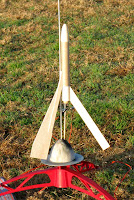


Last up was the new CYCLONE.

During boost, you could hear a distinct whistle from the ejection port hole.

It was a good thing I moved the launcher farther up the field.
At ejection, the upper half did it's fast spin and almost landed in the road. With a 1/2A3-2t engine it drifted about 200 feet away.

Both the UP! CUP and CYCLONE are being developed as Odd'l Rockets kits.

Sunday, December 19, 2010

TOP TEN Countdown for 2010


Taking a cue from Dick Stafford's Rocket Dungeon,
Here's my TOP 10 FAVORITES since starting this blog last July.
(Click on the names to go to the blog entries)

Just a classic downscale.

9. MX-774
Favorite kitbash from an Estes Bullpup kit.

Retro build from 1972

7. Big Girtha - picture at top right
2 engine cluster "sort-of" Bertha

Great new kit from Dr. Zooch

One way to fly the Quest "freebies"

4. Engine Hooks "How To"
Highest number of views

3. Martian Patrol CATO - picture at middle right
Best picture captured by Roger Smith

A great MicroMaxx performer

And the biggest surprise of the year -
1. CYCLONE
Mapleseed Recovery Rocket
Simply amazing on recovery.
You've got to try one of these!
The blog build is coming soon!