Showing posts with label Tube Alignment. Show all posts

Sunday, May 31, 2026

New Way Lunar Jumper Build, Part 8, Tube Fins


While the tubes were still separate,
The edges got a wipe of CA glue. 

Sanding with 400 grit followed.

Using my aluminum angle, 

A pencil line was drawn down all the six tubes.
A glue line was applied down the lower half of the BT-5s,

Pres into the BT-20 tubes lining up the pencil lines.

Here's how the tubes look from the rear, the bottoms are flush.

Apply a line of glue down the pencil lines running down both tubes.


Press into the outside edges of each fin.
Visually center on the pencil line.

Saturday, November 5, 2022

Estes Odyssey #7235 Build, Part 13, Vanes Marking & Gluing

I only marked the location of the root edge length of the cardstock vanes (Parts O) These upper pencil lines were just longer than the root edge of the vanes.

Only one of the lines was extended down to the rear of the body tube to glue on the BT-80 tube.

The instructions show all the lines the entire length of the body tube. I wouldn't do this - thin pencil lines can make slight indents down the tube and show up when the rocket is painted. 
That's a lot of pencil lines!
TIP: Never use a ink pen to draw position lines. In will show through paint!


Here's a picture from further on in the build -
Look close and you can see the scribed pencil indent line between the two fins. 
When you draw pencil lines, don't press too hard. Use a soft pencil.


The BT-50 tube (Part L) was glued onto the single pencil line that ran all the way down the tube.

The primer/filler was scraped off and the tube roughed up before the glue was applied. 

The rear of the tube is 1/2" up from the end of the BT-55 main airframe tube.


Here's the forward vanes glued in place. 
Some gloss white was sprayed over just this area to spot any glue that needed to be sanded smooth. 

Notice the edges that had the sanded glue bead (seals) on the outside edges. The edges are smooth and shiny.

Wednesday, September 23, 2020

Estes Colonial Viper #1310, Part 10, Gluing Together The Four Tubes


The alignment template is cut out. Cut the inside circle arcs first, then all the straight lines with a straight edge.


The older instructions say to lay a glue line down the short tubes, slide them through the alignment guide, then rotate the tube and glue line onto the center tube.

That might leave a glue mess. I like to have more control without leaving glue boogers everywhere.

To start, draw a line down the three short tubes. Sand away the primer right down the line. Re-draw the line.

I'm using very little glue at present, just enough to tack the tubes together. Adjustments might need to be made when the templates are slipped on.
You can glue the bottom two engine tubes on now, without using the guides. They are all even in the back and lay flat with the BT-50 center tube.


Here's the three engine tubes in place using the two alignment guides. 

So far I've used very little glue to set the outside three tubes. More will be added in the next post.


Saturday, April 13, 2019

Quest AS-1 Escort Build, Part 9, Tube Joining


After sanding the gap cap, the tubes are dry fitted.
The two 45 degree cut tubes should fit together.


Here's what I don't understand.

GOTCHA: The center tube has an angle cut - that ends up inside the upper tube.
There's no reason for this interior angle. If it is trimmed back you'll have more room for the parachute.
I did a tape wrap for a cutting edge guide and took the tip off about 1/8" above the gap cap .


On the left is the "pinch hold" while the glue dries.

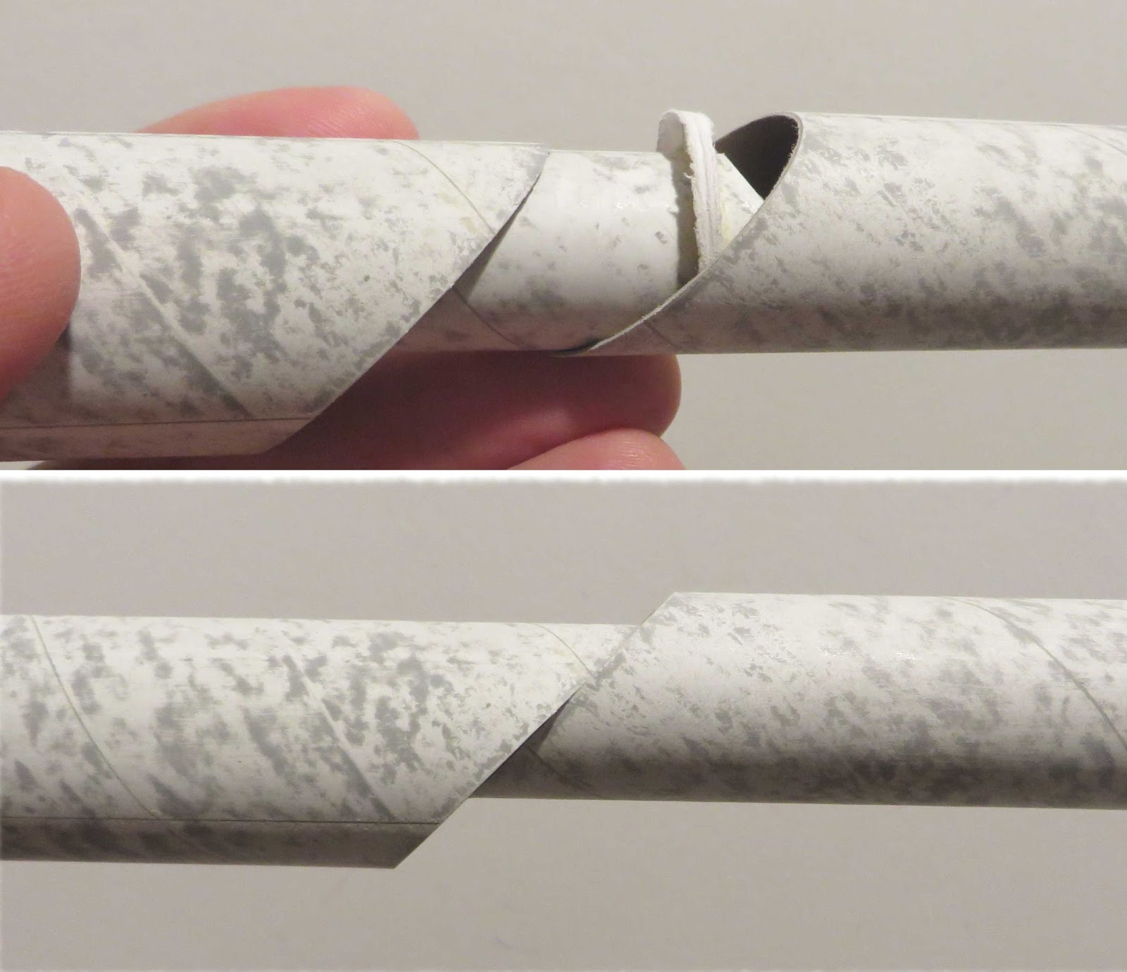
The inset picture shows the alignment of the center lines. Look down the tubes to make sure they are in line.


A drop of glue was squeezed in from the top of the upper tube to fillet the gap cap joint.

Thursday, April 11, 2019

Quest AS-1 Escort Build, Part 7, Gap Caps?


The gap caps are needed so the ejection charge doesn't blow out the back between the offset tubes.
GOTCHA: These are printed on 110 lb. cardstock. While this thickness might work, I would rather have them as thick as a regular centering ring.
I did two more laminations of 110 lb. cardstock.
I was making two models at the same time, two sets are shown.


These are hard to cut out, Quest does supply an extras.
TIP: Cut out the centers first, then the outside lines. Trust me, it's easier this way, if you were to cut the outside line first you have nothing to hold onto when cutting out the center.
Pick and use the better of the two cut caps.


Apply a line of glue 1/8" from the short end of the angle cut center tube.
Oops! I glued the gap ring on upside down. It makes more sense to glue it inward. (See pic below)  Shrox designs are different than anything else out there. Pay attention!
Here's how the ring should be glued on!

The ring edges look thick. This was after sanding down the edges to fit in the forward tube. I left the thick rolled over edge for a wider gluing surface. The rolled edge will be inside, no one will see it.

Wednesday, January 16, 2019

OR Spaced Needle Build, Part 3, Gluing The Tubes Together

This post shows one way to glue together two tubes.
This didn't work for the first build of the Spaced Needle design, the model ended up too long to easily transport without damage.
The next post will show how to make a coupler so the model will break at the mid point.


Before gluing together any two tubes, roll over the inside taking down any burrs left from when the tubes were cut. It doesn't take a lot of pressure, don't distort the tube.
TIP: Before you glue two tubes together, think ahead. Have a clear, clean flat surface to roll the tubes over and insure they are straight. This is a tall model and will require a pretty big area.

A nice bead of glue was set inside the low tube.

The coupler (with Kevlar line tied and attached) was pressed in halfway.
While pushing in the coupler, try to turn it so the glue is spread out evenly.


Drop the long Kevlar line into the upper tube.

Place a line of glue inside the upper tube. Push the coupler in and turn. Don't let the Kevlar get caught in the joint.


The two tubes are rolled on a flat surface, here I'm using a counter top.

Plan ahead - Gluing two tubes should be done fairly quickly while the glue is still pliable, before it sets up.

Thursday, January 4, 2018

Model Minutes Leduc 22 Build, Part 5, Central Tube and Coupler


"General instructions Photography may lightly differ". (Yep, they typed "lightly differ".)
The central tube picture was different than the center tube included in the kit. The tube picture was from a different model.

Even the long central tube can be formed in the palm of your hand. Do one side then flip the card stock over and form the other side.

Be sure the end of the dowel is rounded, otherwise you might get some scarring that could show through at the tube mid-point after it is rolled.
The outside tube coupler was too loose on the lower T1 and upper T3 sections.
NOTE: To the left of the T3 mark is the upper centering ring location. Later in the build I glued the rings right between those lines.

I cut another strip of 110 lb. card stock and rolled a second, tighter coupler.
NOTE: The replacement coupler wrap I made was the exact length of the kit supplied piece. Notice it is set right to the placement line on the lower tube.

Why bring these printed placement marks up now?
I want to be sure alignment would be correct later on, all the lengths and part positions should be correct for the final assemblies. You'll see what happened in future posts.

Thursday, November 10, 2016

Perfect Inline Launch Lugs


An email from Eric James Blitchok -  
Overeasy123 November 4, 2016
Chris, I just had a Rocket Epiphany? After all these years, and all these Rockets? I should be applying my Launch Lugs to the BT with the help of Aluminium Angle, long before approaching the Fins! They'll never be straighter!

A follow-up on November 7 - 
Why was I trying to sight down a Cherokee-D to align the Split Lugs after I’d glued the fins on?  I could easily arrive at perfection with my Aluminum Angle and some planning!  From now on my builds begin with Lugs!  Here’s a photo of my Newly-Discovered Tenet’s Implementation!  (The first of six Mini Maxes I scored in the Estes Sale.  Geez, was it fun gluing up those 13mm Mounts.) 
__________________________________________________________________________

Hi Overeasy,
Great point! That will certainly get a single lug in a straight line or two lugs in perfect alignment.

I tend to glue the engine mount in first, then the lugs, then the fins. 
It's just easier to line up the engine hook and lug on the same side first. Some instructions have you glue the engine mount in last. Then you are dealing glue that might be setting up when trying to turn the engine hook in line with the lug!
If the lug is glued on before the fins, 
Wrap the marking guide around the tube and line up the LL line with the lug already in place,
Then mark for the fins.

Tuesday, July 12, 2016

MPC Red Giant Build, Part 3, Assembly and Launch Lugs

Before gluing everything together, really look at the print wraps on the body tubes. The names on the upper and lower tubes should line up and center between two fins.

TIP: The kit instructions have you put glue on the adapter and fin can shoulders. Instead, put a glue line around the inside of the body tubes so the glue won't squeeze out onto the outside of the model.
I used the Beacon Fabri-Tac glue again with good success.


Here's how the print on the lower tube lines up with the center area between two fins. Look close to see the pencil lines to the right of my thumb. I would have thought the vertical black line would be the center.

TIP: When you have to line up parts and printed tubes, it helps to do a dry fit, pre-marking the center alignment points with pencil.


I decided to put the lugs just to the side of a fin instead of centered between two fins, Mark the locations and span of the lugs with pencil. Scrape away some of the print ink for better adhesion.