Tuesday, December 31, 2013

Centuri Flutter-By Build, Part 6, Paper Laminating Fins


After the fins have dried overnight in a heavy book, the edges get a coat of medium CA.
The CA insures the edges stay down during trimming. It also hardens up the edges for smoother sanding.


Cut all the corners form the fin edge out.
This also makes for easier sanding, the edges can flex when bent by the sanding block.


Cut the sides closer to the fin edges.


Finally,
Sand off the paper edges with 220 grit on a sanding block.
Sand off only the paper folded over the sides, don't sand into the wood.
Don't sand the rounded leading edge.

Centuri Flutter-By Build, Part 5, Paper Laminating Fins


Turn over the fin and apply glue stick to the other side.

With the wood fin leading edge so close to the centerline you can see why the glue overlapped the middle. You can't get close or under the leading edge now.
Here's where most people have trouble with papering fins - the rounded leading edge.
Take an extra moment to roll the paper over the rounded leading edge before smoothing the paper on the other side of the fin.
Be sure the paper is tight and smooth over the leading edge.

Then continue smoothing the paper into the glue on the open flat side.


Burnish the second side.
Press the fins in a heavy book and allow to dry overnight.

You could also paper the launch lug if you want to.
Sometimes that's easier than filling the lug seams with CWF.
Just take your time and be sure the paper covering is smooth.

Monday, December 30, 2013

Centuri Flutter-By Build, Part 4, Paper Laminating Fins

Instead of the strakes the fins will be reinforced with paper lamination.
Mentioned earlier, this is the way the original kit  fins were strengthened.

Only the leading edges of the fins were rounded.
Trace around the fins, then add a second line about 1/2" outside the fin border. This second line insures coverage and keeps the glue on the paper and off your work area.

Cut the four tracings with scissors just outside the wider 1/2" pencil border.

Apply a smooth glue stick coat. Just glue one side for now.
Be sure the edges are well coated.
Go beyond the center line. Once the fin is set down you won't be able to get glue close to the leading edge.

Set the fin down with the rounded leading edge slightly away from the center line to allow a roll over of the paper.
I've switched over to a clean hard surface, the back side of a hard cover book. The corrugated cardboard I was working on won't allow smooth burnishing.

Turn over the fin and burnish with a smooth tool. work from the center out making sure the leading edge is smooth with no wrinkles or raised areas.

While the glue stick gives you some working time before setting up, you should work quickly.
Go to the next post and continue with the other side.

Centuri Flutter-By Build, Part 3, Engine Mount

There is no mention of a relief notch on the inside of the adapter.
You should cut one or the engine mount tube will be distorted where it presses down over the engine hook.

TIP: Don't cut the notch over the seam. The ring will want to de-laminate if the seam ends are cut.


The centering ring will have to slip into the outer BT-50 tube.
Round off the edges with some 220 grit.


The green layer is thin and may start to peel up on the edges.
Brush on a coat of CA on the edges.
Lightly sand smooth with 400 grit.
Here's the finished engine mount.

TIP: I also cut the notch for the engine hook so the exposed motor tube seam wouldn't go underneath the hook.
Now I can fill and sand the seam without the hook in the way.

Sunday, December 29, 2013

Centuri Flutter-By Build, Part 2, Fins

In the original Centuri kit, the four Flutter-By fins were the same.
The two fins on the left are used in the bottom half. The tab on the root edge glues to the smaller diameter engine mount tube.
On the right are the upper section fins with no root edge tab.
All four fins have strake positioning lines burnt into one side of the fins.

Below are the reinforcement strakes, not part of the Centuri kit.


The strake lines are burnt halfway through the wood!
Why would you reinforce a fin that has a line cut halfway through it?

Check the old Centuri instructions at www.oldrocketplans.com HERE
The instructions mention an "Optional Strengthening Technique" in Step 6. This is simply gluing copy paper over the fin. I'll be explaining the technique coming up in a blog post.
The instructions on oldrocketplans say the fins were 1/16" thick. I don't remember them being that thin. These fins are 3/32" thick.
I'm fortunate to fly on grass fields. The paper laminated fins should be plenty strong landing on grass.
Besides, I don't like the looks of the strakes.


After the burnt edges are sanded off, stack the fins as best you can and round the outside corner. Sand this round with all fins at the same time for consistency.

Round only the leading edges on all the fins.

New Harbor Freight Score!

Here's the old standby, the X-Acto #11 blade.
I've seen them in the hobby stores for as much as $5.00 for a five pack.
It seems they were always changed (before they were dull) when the brittle knife tip broke off.

Last year I got my "go-to" knife, the Olfa XA-1 at Home Depot for a little over $5.00. (There are cheaper break-off blade knives, I did want one that fit the hand and was sturdier.)
Next to it is a 10 pack of Olfa 9mm replacement blades for it. Also, for about $5.00.
There it 13 new sharp tips on each of the 10 blades.

When you do the math, each new break-off tip is just over $.04 each!
Since getting the Olfa knife I rarely use the X-Acto anymore.

If you've never used a break-off blade knife before - 
There is a little "play" in the knife blade. These are utility knives and don't "lock" as tight as the X-Acto style knife handles do. Like any new tool they might take some getting used to.
But for the cost savings and always having a sharp knife tip it's worth the compromise.


Harbor Freight sells a 10 pack of the 9mm blades for $.99!
Each new sharp tip is $.007 - less than a penny each!

The Harbor Freight probably aren't stainless steel like the Olfa brand.
Sure, the packaging isn't as pretty and there is a slight bit of corrosion on the blades - my balsa doesn't care. These blades cut just fine.

Saturday, December 28, 2013

Centuri Flutter-By Build, Part 1, Parts

Here's some back story on the Flutter-By from the Semroc Spartan kit instructions:
"The Stellar Spartan was the second in the Centuri Stellar Line. Originally planned for mass merchandising, the line was later changed to mail-order only, then dropped. The Spartan was an early prototype for the later Screaming Eagle which replaced it. Leftover parts from the Spartan were used for a few years on the Flutter-By until they were gone."
Looking at the Spartan fin profile, you can see it's the same fin.

The "Flutter-By" - not a very macho rocket name.
I had an original Centuri Flutter-By in the mid 1970s.
As I remember, it performed well with A8-3 engine's.


I bought two Flutter-Bys in the recent Estes Clearance Sale.
I put off buying the re-issued kit because the price was too high.
Up until the sale the retail price was $14.29!!!
High - considering how few parts are in the bag.
In the picture above notice the laser cut lines for fin strake positions.

Parts of interest:
The nose cone is longer than the Centuri version. The original was a Centuri PNC-80, 2" long. This nose cone is 3 1/4" tall.
The drawn lines on the decal are thick compared to the original kit.
It's missing the chrome trim included in some Centuri kits at the time.

I'll be referring to this one as a Centuri Flutter-By.
I won't be using the strakes and will try to make it look a little more like the Centuri catalog picture seen HERE.

Quest X-30 Aerospace Plane on RocketReviews.com

I did a stop at rocketreviews.com to read the daily build review.
A few years back, Mark Fisher did a review of the Quest X-30 Aerospace Plane. HERE
Here's a excerpt:
"Don't believe the placement dimension given in the instructions for the stern (i.e., larger) bulkhead; fit it up last, after you make sure the bow bulkhead is even with the edge of the body wrap. Even with careful work, my X-30 looks like a golf shoe."

Well, it does look a bit like a golf shoe. That did make me laugh. It always gets attention at a launch. 

You can rig it to hang horizontal after ejection. It's all covered in the blog build HERE.
Scroll down a few posts to see how I did it. 
The instructions mention it can be done but don't give any real directions.
Take extra time packing the two parachutes. I've had only one eject on the first flight. The second flight I used just one chute. The model is heavy and does need both parachutes.

The X-30 is a Level 4 build but sometimes a change in materials and techniques is a good thing.
JonRocket.com has them available! HERE

Friday, December 27, 2013

Estes Gyroc Finished


This build was a bit frustrating but brought back a lot of memories.
The elastic tie positions from the Estes instructions didn't give enough pull so they had to be moved.
Look close to be sure you have covered every area when painting this one.
The fins look straight from all sides but the Gyroc wants to do a slow spiral during boost.
This model was designed before "shotgun ejections". There is a loud POP when the engine ejects.

This one is a fun build using spare parts and some 1/16" thick balsa.
Or just get the BMS clone kit, at $10 it's a great buy!

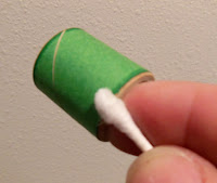
Another Q-tip TIP!

A wet Q-tip makes a perfect tool for smoothing out a decal.
Wet the Q-tip by dipping it in water.
Roll the Q-tip from the center working out water and air bubbles from the center to the outside edge. Roll the tip, don't scrub over the decal.

I don't know how I got by in the past without using cotton swabs.
They work well smoothing out fillets where your finger can't reach.
The plastic tubes (on generic store brand swabs) are used on removable Kevlar engine mounts.

Thursday, December 26, 2013

Estes Gyroc Build Part 11, Elastic

After this step I remembered having the same problems with my first Gyroc build in the 1970s. There was a lot of tweaking to get the elastic to fully pull the flap against the rudder fin stops.

Enlarge the picture an you'll see where the instructions recommend setting the elastic holes. I marked the hole positions with a pencil dot.
The holes were made with a needle before threading the elastic.
TIP: Find the thinnest needle that you can still thread the elastic through. You want the hole to stay small!
The lower hole (near the hinge) didn't give enough pull on the flap. I had to go higher on the flap.
Now I'm stuck with an extra hole on the flap - Oh well!

Behind the flap is a double overhand knot. Over the rudder fin the elastic is looped and sewn through a second time.

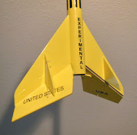
The flap had to be trimmed at the root edge (Below the "A" in EXPERIMENTAL) so it couldn't bind when pulled open by the elastic.
If I were to build another Gyroc, I'd make the root edge of the flap a hair shorter so it couldn't rub against the body tube.
EDIT: Check the previous post for corrections I should have made!

When the elastic is tight enough the flap should lightly "click" against the rudder when released.

When all is right, put a small drop of white glue at the thread holes.
TIP: Never use CA (Super Glue) on shroud lines, shock cords or the elastic used here. The CA glue will run up the lines and harden it.

The white glue helps hold the elastic knot tight. Use just enough to hold it but also allow replacement of the elastic if needed later on.

Gyroc Part 7 Post Corrections!

There was reasons I had trouble with the Gyroc flaps!
My Gyroc flaps needed trimming to clear the body tube when flipped.

I'm the type that follows instructions.
Didn't G. Harry Stine say: "When all else fails, try following the instructions!"
I had built a Gyroc years ago, maybe I thought I was past following the directions.

I try to keep up on the comments from blog readers and respond to questions.
"Anonymous" made comments on the Gyroc, Part 7 post from December 23 -
He was right in his observations. This one deserved answers and a blog post.
"Anonymous'" comments are in Italic

Actually, instructions call it "fin-flap" assembly, not "flip-flap".
You are right! That's what a tired dyslexic gets for trying to read directions at 2 a.m.!


"Noticed that you matched up the flap root edge with the fin and left that portion of the edge square. If I'm not mistaken, there was supposed to be a slight gap between the flap root edge and the body tube (if you take the parts templates from the pattern sheet and lay them out, you'll find out that the flap is slightly shorter than the fin. Also the instructions show the root edge of the flap portion to be rounded rather than left square). Although having the flap root edge seating tightly against the body tube might give a cleaner appearance, you'll probably run the risk of the flap binding against the body tube - especially after primer and paint."

That's what happened!
Putting the two pattern sides together I saw the slight gap at the root edge. If I didn't sand the root and outside edges even with each other, the fin flaps would have worked without trimming later on.


This didn't help much!

I cut the the pattern with the outside edge of the flap (on left) a hair wide. 
When I stacked the two fin pieces I gang sanded them to match up the root and outside edges.
Step 5 illustration shows the upper fin half slightly wider than the lower half. It's subtle, but it is there. I didn't notice it. 

"As far as the positioning of the fin-flap assembly -- I'd interpreted the general layout illustration to indicate that the hold-down tabs should be attached to the flap near the "corner" at the root edge of the flap (where it flares out), and that the forward edge of these hold-down tabs would need to be set back far enough to clear the rear edge of the body tube, but not so far back that the hold-down tabs would protrude below the rear edge of the engine when it is inserted. This pretty much ends up determining the location of the fin-flap assemblies."

That's where they ended up. I wish the instructions went into more detail. The drawings were smaller and confusing. You'd think I would know how to do this by now!

Anonymous - thanks for the comments, I appreciate the feedback. 
Let me know if anything I write raises questions.

Wednesday, December 25, 2013

Top Ten Blog COUNTDOWN from 2013

These are my favorite posts and models from the past year.
Some posts were great surprises or just good builds. Other posts reflect some "game changing" parts.
The new BP Estes E and F engines should be on the list, but I haven't flown any yet.

Counting down from 10 to 1 - Click on the names to go to the posts:

10. WARPED
Building a model around a melted nose cone.

9. KNOTS
Game Changer: A new knot for screw eye tying, the Duncan Uni Knot.

8. 1969 ESTES ALPHA
A fun decal drawing project to duplicate the old catalog model.


7. QUEST AEROSPACE ONE WITH A D12-5
I was nervous before flying this one with a D12, but the results were great!

6. HEAVY DUTY BT-50 TUBING
Game Changer: Not really a BT-50 but a thicker walled ST-9 tube.
5. CLEARANCE & BIG SALES
ESTES 
BP HOBBIES
Estes gave an early Christmas present with a short lived sale.
The BP Hobbies Quest clearance provided plenty of Quest A6-4 and B6-4 engines.


4. FlisKits MMX SATURN V
A tough build but finally, a great flying MMX Saturn

3. NEW MINI ENGINE HOOK
Game Changer: It was about time Estes re-designed these mini engine hooks.

2. CHEROKEE GOON
Perfect model for all my Quest B6-4s.


And the #1 Blog Post from 2013 - 

1. BIG GIRTHA SAGA
A good story, a lost rocket and a recovered video camera that still works!


Not a "Top Ten" - in memory: Sad News from Semroc


Total flights for 2013 was 141, ten more than the 131 launches in 2012.
25 models were built and finished in 2013.
Where am I going to store all this stuff! Good thing I'm single.

You can visit the 2012 Top Ten2011 Top Ten and 2010 Top Ten lists. 
Click on the names!

Estes Gyroc Build Part 10, Paint and Decals

Here's the Gyroc after the first white undercoat.
This is a tough model to spray and even harder to sand smooth. There is just too many inside angles to cover!

On the left shows after wet sanding with 400 grit. The nose cone / body tube seam is gone.
There was still some small "sand-thrus" into the gray primer. Sometimes you can touch up the undercoat. The Rusto 2x paint melds into itself pretty well and saves you from spraying again.

I sprayed a small amount into a disposable cup and touched up any gray.
The picture shows more paint on the brush than I would normally use to touch-up.


Here's the Gyroc after the Yellow sprays.


The black decals are applied. It looks close to the 1970s catalog picture.

The elastic ties are next.

Tuesday, December 24, 2013

Estes Gyroc Build Part 9, Hold Down Tabs

Whoops! I primered the model before gluing on the hold down tabs!
This is right up there with forgetting the launch lugs and not noticing until you go to slide the rocket down the rod.

The instructions didn't make much sense back in the 1970s or now.
Looking back to my first try at the Gyroc, I probably glued them on upside down. I thought the tabs were used to friction fit against the engine - not so.
With the tabs in "neutral position" (the flaps held straight down) the tabs fit on either side of the round engine casing.


I sanded away the primer to open up the balsa for a strong glue bond.

Notice the flat side of the tab is up, the angled inside edge is down.

Look close and you can see how the tab sits beside the curve of the engine casing.

The inset picture shows the tab sicking out a bit from the edge of the flip-flap.

Estes Gyroc Build Part 8, Gluing the Rudders


When setting the rudders, raise the flap to be sure it makes contact on the trailing edge of the rudder.
Again, don't use much glue. Lightly tack the rudder in place, you'll probably be adjusting it later on.

Here the rudder was glued with it's root edge right beside the pencil line from the last step.


The placement of the rudders facing the raised flaps is more critical than the opposite rudder. Glue the flap facing rudders first, then glue up the rudders on the other side.

From the side, be sure the rudder leading edge tips are in line with each other.


From the back, be sure the rudders are in a good cruciform shape.

Everything got white glue fillets, then a final fillet of Titebond M&TG.


The 90 degree angle is too tight for your finger.

I used a Q-tip to smooth the fillet in the root edge areas.