Showing posts with label Adapter. Show all posts

Tuesday, March 25, 2025

Aerotech Mega Initiator #89541, Part 10, Final Fin Fill & Dry Fits


The fins on the flight version were left square.

That inside leading edge angle still wouldn't match up. I added some CWF for a better flow.


Here's the same fill after sanding. Some 400 grit was wrapped around a pencil to sand the angle.


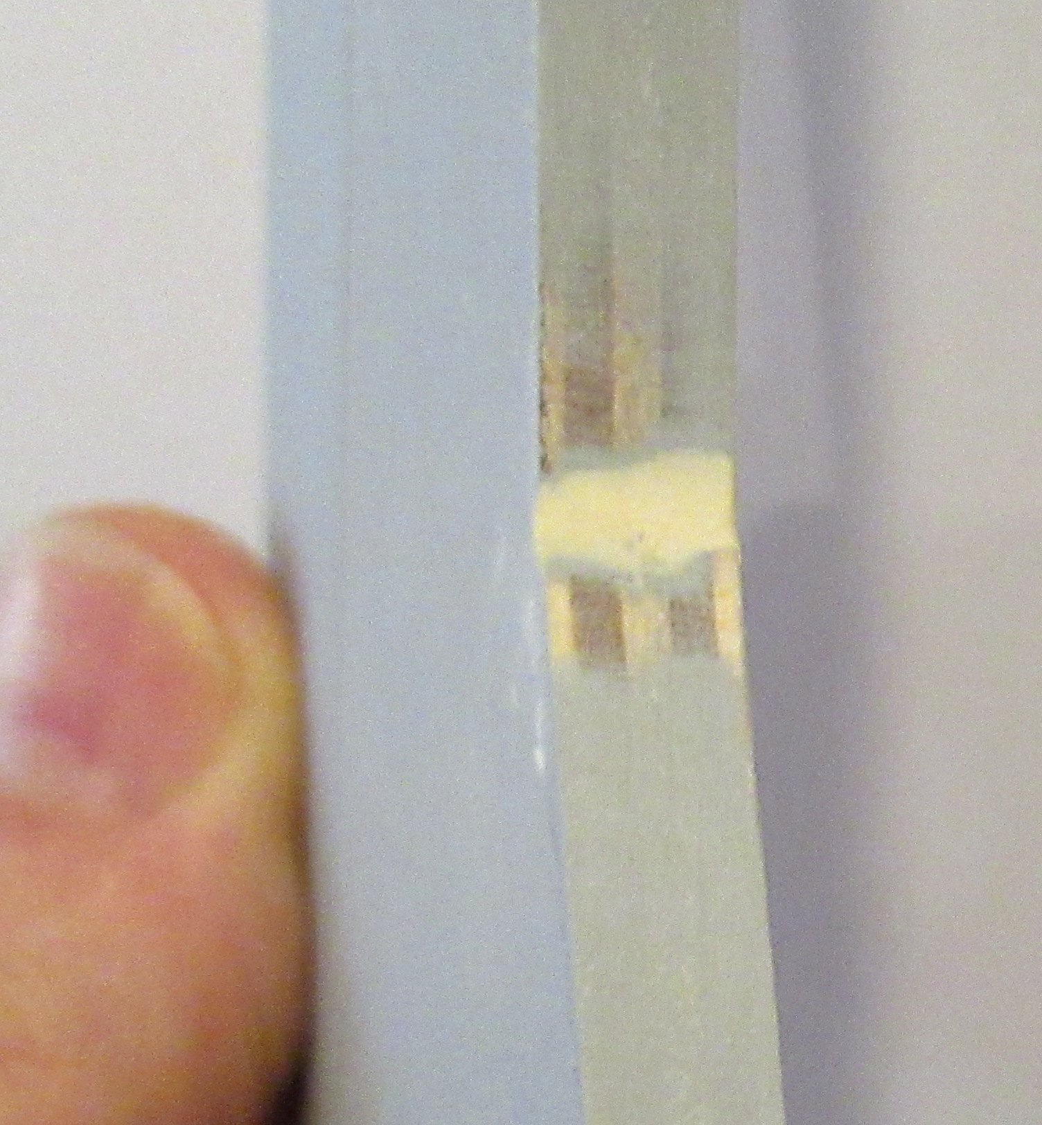
Another dry fit of the fins showed the ring slots were too tight.

The sides were shaved down, widening the slots.


Here's how far the engine mount is recessed, the ring face is just under 7/8" from the end of the tube.

With the fins in the slots set the placement depth of the  engine mount.

Monday, March 24, 2025

Aerotech Mega Initiator #89541, Part 9, Assembling The Engine Mount Adapters


In the last post, I did some dry fits until the rings were tight on the tube, but still moveable.

Here I'm using the flat face of my sanding block to get the lower ring flush and square with the end of the motor mount tube.


Here's the engine mount ready with the upper ring 1" from the top of the tube.

A dry fit ready for the epoxy fillets.
Epoxy fillets were applied with a gloved finger and smoothed with alcohol.

In the picture, I've applied a fillet and am removing most of it with a Q-tip. This is the ring that "sockets" into the larger engine mount tube. You don't want excess glue to hinder the fit.


The finished adapter.

The other two mount assemble and glue up the same.

Monday, December 16, 2024

Estes Constellation Build Part 10, Nose Cone and Adapter Details

On the left is the nose cone and adapter from the Semroc kit.
You'll see these shoulders through the clear payload section when the model is finished. I usually sand these flat then round the edges.

On the right is the dry fitted payload section with the rough ends smoothed out.

TIP: To get a sharper edge on a balsa nose cone shoulder -

Brush on some CWF just slightly over the edge.
I'm not covering the entire nose cone yet, just the shoulder edge. this leaves the nose cone dry to hold on to it.

Slide the nose cone shoulder into a squared BT-50 tube.
Turn the nose cone and CWF on the shoulder onto the tube top edge.

Turning the nose cone base forces the CWF into the shoulder lip.
In the picture you can see the raised ridge of CWF at the bottom.
Slide the nose cone back out and let dry.
Sand off the raised CWF ridge with a block.
The nose cone shoulder lip will be stronger and the edges sharper.

Thursday, August 1, 2024

Enerjet by Aerotech, Astrobee D Build, Part 5, Engine Mount & Upper Tube Bulkhead

Gotta' love instructions when they get things right!
Something I've been harping about for years -
1. Use a Square Knot to tie a shock cord to the screw eye. A "Granny knot" can slip!
2. Do not put cement on a knot! Cement (glues) will weaken the shock cord.


The ejection baffle is glued into the top end of the tube. In the last post the 1/4" slits were cut in the top of the tube.

The second centering ring is glued onto the top of the ejection baffle.

The screw eye is screwed into the hole in the top of the ejection baffle.

The shock cord is tied to the screw eye with a square knot.


Jumping ahead to the Upper Body Prep and Assembly:

The screw eye is turned into the bulkhead plate.
Be sure not to screw in too far. Leave a bit of the threads still visible. If you screw in too far, the screw eye won't hold.


Tie on the second shock cord with a square knot.

The plate is glued onto the coupler with the screw eye facing down.


I applied a wood glue fillet on the inside joint using a Q-tip taped to a dowel.

Monday, May 2, 2022

New Way Mars Snooper II, Build, Part 7, Vanes & Balsa Adapter


Just like the balsa fins - 
You should clean up the laser cut edges with 320 grit.
Left as is, the cardstock vane edges will soak up paint and end up looking rough.

Run a thin bead of white glue down the edges that will be exposed.
Smooth down the sides with a finger leaving a round bead of glue.

After the glue dries, sand smooth with 400 grit.
You'll end up with a rounded, glossy finish edge after painting. 


The balsa adapter was a bit wider than the outside diameter of the tubes. 


The sides were sanded using my block.
Slowly sand and check, then sand some more.

Monday, December 20, 2021

Estes Skylab #001973, Build, Part 8, Third Stage Adapter Shroud

Here I haven't glued the cardstock shroud in place yet. It is taped to hold and "form" it to the tube diameters.

TIP: Before laying down any tape - reduce the tackiness by pressing the tape on your pantleg. Press and lift, press and lift. Do this a few times so there is less chance of the tape tearing the card stock when the tape is lifted.

On the right side picture - Note the overlap of the card stock shoulder. This edge will be much thicker when the vacu-form wrap is in place. 
Try to fit the shroud edge evenly over the adapter tube top.


Even though the tape is not very sticky, carefully lift the tape.

Don't glue the shroud in place yet - see the next step.


Here's how the instructions show the shroud gluing.
The gray bands imply more glue than is needed.

I would only apply glue to the upper edge of the adapter - just to the left of the arrowheads in the above drawing. 
Make the glue bead small.
Slide the shroud down and seat the edge on the line of glue.

Then - apply a small bead over the joint, 1" at a time and remove excess with a finger.
This will all be covered with the vacu-form body wrap reduction piece.

Thursday, December 16, 2021

Estes Skylab #001973, Build, Part 5, Third Stage Adapter

NOTE: Save the centers from the centering ring for Step 5 of the instructions.
Notice the ring in the right picture. The ring is set inside the edge of the 1 3/8" long tube.
 
GOTCHA: The instructions say cut a 5" length of shroud line. In order to double and tie it easily - cut a length of at least 10".

I used #10 embroidery thread which is much stronger than the current shroud lines supplied in the kit.
Use tweezers to make the knot tie easier.

Here's the fit of the adapter of the in the top of the tube.
I did have to sand the adapter for a better slip fit.

The tube seams were first filled with CWF and sanded to surface.

The picture on the right is a fairly thick coat of Duplicolor Filler/Primer in the second step of the seam fill.

This shows the saved ring center glued in place.

I also treat the low adapter corners (at the top here) with some CA glue applied with a Q-Tip.
After that glue dries, round off the edges with some light sanding.
This makes it easier to slide in the upper section later on. 
If the adapter edge is smooth and rounded it won't wear or peel the inside layers in the lower body tube.

Thursday, September 16, 2021

Estes Super Mars Snooper #7309, Build Part 6, Seam Filling


The new nose cone and transition molds are very clean!
You've really got to look close to find the seams.

It just took a little sanding to smooth them out.


Body tube seam filling - 

Here's two BT-55 lower tubes from two kits.
On the left is the thinned CWF filler applied by dragging a knife blade down the seam, a little at a time. Dip and drag, dip and drag down the seam.

On the right side is a filled tube seam, sanded to surface.

I do a two-step tube fill process.
After the CWF has been sanded down, Duplicolor filler/primer is sprayed.

On the right side is the filler/primer sanded to surface. Look close to see some gray filler/primer left in the seam, filling what recess that was left.
The CWF fills about 75% of the seam, the remaining 25% is filled by the filler/primer.


As mentioned above, the nose cone and new adapter were very clean.

After lightly sanding the filler/primer, there was really no seam to fill.

Saturday, June 19, 2021

Estes Indicator #7244 Build, Part 6, Engine Mount Gluing & Adapter Fill


The instructions imply that the rear centering ring is even with the low edge of the body tube.
The picture shows a dry fit, no glue yet.
If you recess the lower ring about 1/16", you can add a glue fillet along the bottom joint.

I like to use a dowel to apply the inside ring of glue for the upper centering ring on the mount.

Set the dowel next to the mount and mark just below the lower ring. With the glue bead (in the tube) slightly below its final position, you will push the glue up creating an interior fillet.
Don't use too much glue - the tube could shrink in as it dries leaving a "Coke Bottle" ring depression.

On the left I'm rolling the glued dowel around the inside of the tube using the pencil mark as a depth gauge.

Turn the mount as you slide it into the glue ring, making a more even interior fillet.
The engine hook is in line with the two launch lugs.
There is two small dents where the adapter was twisted off the mold tree.

I fill them with a dot of medium CA glue. A drop of CA will take a few minutes to dry before sanding to surface.

Note the adapter is slid out a little so it won't be glued into the tube yet.

Thursday, June 17, 2021

Estes Indicator #7244 Build, Part 4, Fins & Adapter


Here's how the two piece fins will glue up.

There are six fins total, two pieces per fin.

Glue these up against a straightedge. I like to set some small weights on the glue joint seam so both pieces end up flat.


The upper fin root edge is glued to the body tube - 
The root edge on the low fin is angled to fit the 20/50 adapter. 


Speaking of the adapter - There is a tie down loop on the top.
I would think this might stop the ejection charge. Except for an open rectangle space under the tie loop, this seems like a blockage.

This question came up on a forum. Estes replied that it doesn't impede the ejection charge or deployment of the parachute.


I cut the end off using a razor saw. 

Here's the new open top end after rounding off the rough sawn edge.

Saturday, January 9, 2021

Semroc Laser X, KV-33 Build, Part 2, Adapter Assemblies


You make two adapter assemblies, one for the engine mount, the other for the mid body adapter.

The centering ring with the two holes is used in the upper adapter. A Kevlar loop is tied through the two holes. Some Centuri kits used a shroud line to tie the model together instead of a screw eye in a balsa adapter.


TIP: The coupler ends can be sanded for a flatter gluing edge.

Tubes and coupler ends are usually cut at a slight angle. 


The centering rings are glued onto the coupler ends.
Lay the glue bead with a bit more on the inside edge. Set the ring on and twist it, making a more even inside fillet. 


You can smooth the interior fillet and remove excess glue using a Q-tip. 


The Kevlar in this kit was braided. To prevent fraying you can rub some white or wood glue on the ends. 
TIPS: Never use CA (super glues) on string, cords or knots. CA glue will make the line hard, brittle and easy to break.
The instruction illustration shows a bigger loop than is necessary.

Sunday, August 9, 2020

Estes Green Eggs, #7301 Build, Part 9, Color Choices & Payload Mask

Here's the original 3 engine cluster Scrambler from the 1974 Estes catalog. It was designated kit #K-37.
Overall white body, one white fin, one orange, one black.
The nose cone is also orange.

Notice the black areas in the payload section. I would assume these were black sponge disks to cushion the payload. Foam disks were included in the Shrike kit.
The nose cone shoulder and adapter shoulder areas are also black. I'll mask and paint the clear green payload section black like the picture shows.

The Green Eggs kit will capture the feel of the old Scrambler even with the clear green payload tube.

The coupler/adapter has a raised ring in the center. The adapter is molded yellow with the nose cone.
Interesting with a good coat of white paint it still shows some yellow. The yellow nose cones in my Odd'l Rockets F-104 and F-15 kits have yellow plastic nose cones. If you don't prime and cover the yellow, some of it could show through after the paint dries.
This isn't a problem with the nose cone, the yellow plastic is a good color under the final orange paint.


The payload tube mask is on the left.
Clear Scotch tape masks the initial line, masking tape and paper wrap covers the middle.

On the right is the mask after the tape is pulled.
If you've never tried a Scotch tape mask before, the smooth clear payload tube will give some very sharp color separation lines.

Wednesday, November 6, 2019

Estes Little Joe 1, #7255, Build Part 12, Filler / Primer


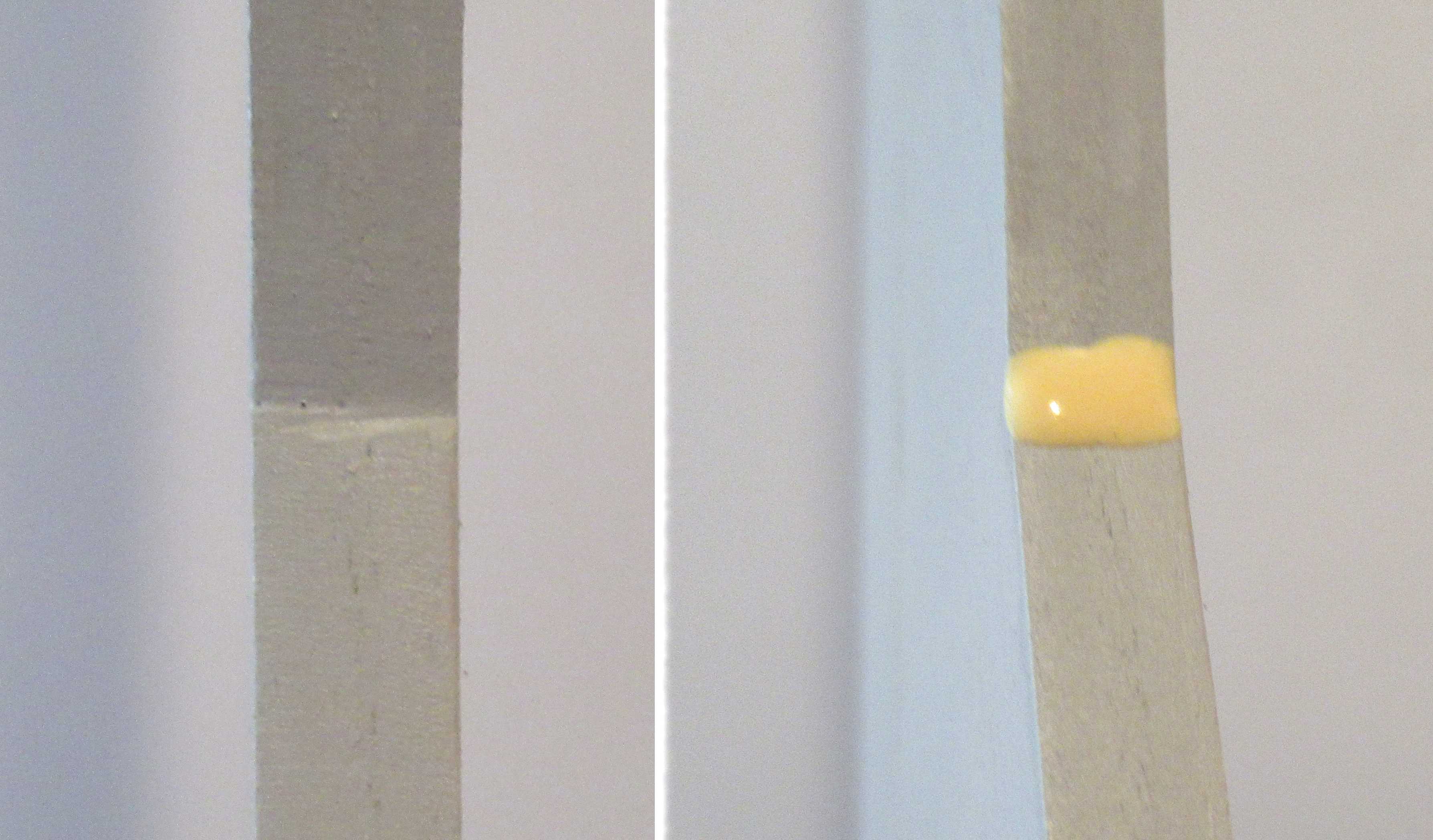
Here's the main body after a shot of the Duplicolor Filler/Primer, before sanding.
The primary tube seam has been filled, but this tube has a second recess seam under the clear glassiene wrap. Most all of this second recess should be filled with the filler/primer.

The fins were taped down to a sheet of cardboard for their shot of filler/primer.
Note the TTW tabs are covered with tape for a clean gluing edge. The root edges are also covered.
Here's one fin before and after sanding the filler/primer with 400 grit.

On the left, notice the card stock edge slightly overlaps the root edge balsa piece to better fit the curve of the body tube.

The second picture shows the sanded trailing edges. You can see the tabs showing through with most of the filler sanded off.


The shroud seam was smoothed.

There is a problem with my shroud. The top diameter fit is perfect, but the lower, larger end is a bit too small! At the seam bulge it extends outside the lower tube. I may have to do some filling and "feathering" later on.