Showing posts with label E Little Joe II. Show all posts

Saturday, July 22, 2017

Estes Apollo Little Joe II Finished!


On the left is the removable for flight engine nozzle plate.


Here's another one I can cross off my list! I wanted this kit when Centuri produced it the first time around.
The wrap decals are thin and tricky.

A very impressive model when finished. Thanks to Estes for bringing this one back!

Friday, July 21, 2017

Estes Apollo Little Joe II Build, Part 44, R.C.S. Nozzles

You have to remove the "X" box from the decal.
Once it is cut out it would be very hard to see the location when gluing. I wrapped a strip of paper around the body and marked the locations with pencil.

When removing the squares, cut lightly! You are only cutting through a thin clear layer and not into the paint. The RCS nozzle base barely covers the inked square.

I was very surprised when pulling up the clear decal that the X box black outline was left on the body! (See inset above) This will require some very light, careful scraping to remove the black lines. You don't want to scrape deep into the paint, just remove the black lines.


On the left shows the box after scraping. I used a medium super glue for plastics to attach the nozzle housing.
Since I didn't attach the shock cord at the upper centering ring slot I needed to cover this up. Some of the ejection charge could go out the back. I saved the pieces from the doubled centering ring and it fit perfectly. In the picture on the right the piece was set next to the open slot.

TIP: To set the piece I taped it to a dowel. Glue was applied and the piece pressed in place over the slot. The dowel and tape were pulled free leaving the patch.

GOTCHA: I did  pull on the 24" parachute shroud lines - they easily broke. I'll replace those lines with #10 cotton embroidery thread.

The body will descend on the Estes 24" parachute. The tower and capsule will use a 12" or 15" Odd'l Rockets chute.

Thursday, July 20, 2017

Estes Apollo Little Joe II Build, Part 43, Vertical UNITED STATES Decal


When piecing together the long decal pay close attention to the spacing between the A and the T. That's the same amount of spacing you want between the bottom of the T and the top of the E

The only place where I couldn't form the decal with the Q-tip tip was at the top of the raised horizontal band near the bottom of the T.
Before the decal was dry I cut small slits and then used the damp Q-tip to work the air out.


Looking from the bottom up you can see how well the decals conformed into the corrugations.

I had some Micro Sol handy but didn't need it! I don't like using solvents unless I have to.

Estes Apollo Little Joe II Build, Part 42, Vertical UNITED STATES Decal


This was another decal I was concerned about, trying to to get it evenly into the corrugations. I thought this was mentioned in the TRF builds - I cut the line right below the "T" in STATES where it goes over the raised band.
On the right is how I cut the second decal tapering the clear area to the bottom of the T. This taper cut helps the decal fit into the end of the corrugation above the ridge separation.


Look close and you can see pencil lines for a center line. One raised corrugation runs right through the center making it easy to line up the "I"s and "T"s.


The thin clear coat made it difficult to apply the large wrap. On this decal the thin surface made it easier to conform to the corrugations.

TIP: Wet a Q-tip and roll it into a rounded point. This got into the corrugations easier than a brush could.
The Is and Ts were lined up on the center raised corrugation. I started running the pointed Q-tip in the adjacent rut from the center to the top, then center to the bottom.

Wednesday, July 19, 2017

Estes Apollo Little Joe II Build, Part 41, Body Wrap Decal

Again - DON'T TRY TO TRANSFER THIS LARGE, THIN DECAL IN ONE PIECE! Just ask anybody who has had big trouble with the large Mega Red Max body wrap decals.

Slide the decal off the backing about 3/8" of an inch at a time and smooth out the bubbles and water with a damp Q-tip.
Check to be sure the black box sides are in line with the vertical corrugations. Set a ruler down the corrugations and over the sides of the black squares.


I set that line of "dots" (rivets, screws, whatever) about 1/8" from the top of the corrugated wrap.

Again the picture shows the decal segment set down slowly keeping the backing paper on while the transferred part is smoothed out. When the bubbles and wrinkles have been removed slide the backing another 3/8" over and smooth again.


One segment of the decal wouldn't come off the backing paper leaving a hole in the middle of a block.

The inset shows me trying to rub and slide the remaining black smudge. It wouldn't move.

Positioning the body wrap decal was a bit stressful but can be done. After you've set the decals on the command module cover decide for yourself if you'll need an additional clear coat to thicken up the big wrap decal for easier transfer.

Here I filled in the decal break "hole" with a Sharpie. (Where would I be without Sharpie pens?) It's not perfect but a pretty good patch. I still might put a actual black decal piece over this ink cover.

Tuesday, July 18, 2017

Estes Apollo Little Joe II Build, Part 41, Paint Mask and DECALS!


The simple tube mask went well, at the top of the corrugated wrap the line is sharp.


Here's how the bottom turned out after a few rounds of spray paint and light sanding.

This is a great kit - except for the decals. 
The clear coat is very thin! That's a good thing on smaller decals, the clear coat is almost invisible.
I could have added a spray of clear acrylic but I wanted to transfer them as is, like an average modeler might.

GOTCHA and TIP: The large body wrap would be nearly impossible to place in one large piece. Even when cut into sections it is still tricky.
You should cut a segment as you need it so you won't loose the correct placement order.
More in the next post - 

Estes Apollo Little Joe II Build, Part 40, Finally - Paint!


I did wait a few more days to be sure the gloss white was dry.
I thought this would be an easy second color, a simple mask around the body, right above the top of the corrugated wrap.

Scotch tape was set down. The inset picture shows the edge being burnished with a Q-tip.
Above that is brown masking tape and a wrap of copy paper.


Before spraying on the aluminum paint the entire lower body was brushed off using a 1" wide chip brush.
I don't use tack cloths. They can leave a sticky residue, especially when new.


Here's where I hit a snag.
When the small detail pieces were glued on I did touch some liquid plastic glue on the sides. Not completely around the edges but just here and there.
The liquid glue almost disappears - but when paint was sprayed on those glue coat areas wrinkled the paint.
I had to go back and lightly sand. Spray and sand again. With each coat of sanded aluminum the wrinkles got smaller and smaller.
Aluminum spray paint is usually easy. It goes on smooth and quickly dries.

Saturday, July 15, 2017

Estes Apollo Little Joe II Build, Part 39, Main Body Shock Cord Anchor

I'm not painting the lower half of the body for a few more days. I want to be sure the paint is fully dry. This paint drying delay has thrown off my posting schedule - hang in there!
The paint feel dry to the touch, for now I can glue in the shock cord anchor.

I went back to the original Centuri instructions to mount the shock cord. I don't like attaching a rubber shock cord to the engine mount, too close to the ejection charge.

In larger body tubes I had always liked this Centuri method, the simplicity of using a split piece of body tube to anchor the shock cord.
I cut a 1" long section from some scrap Quest 50mm tubing. The tube split was cut with scissors. The body tube piece in the Centuri illustration looks to be about 3/8" tall.

Directly opposite the cut split a 1/4" wide elastic was tied on using a Duncan Uni Knot. Centuri had you attach the shock cord with narrow strips of tape.

This body tube strip was much narrower than the diameter of the Little Joe II. It was gently bent to make the it fit the inside of the tube.
The glasseine was roughed up with 220 grit sandpaper. It was glued in, far enough down not to interfere with the shoulder of the command module.

Wednesday, July 12, 2017

Estes Apollo Little Joe II Build, Part 38, Paint Limbo!


Heat and humidity slow down paint dry times here in the South.
While the main body white looks dry I'll play it safe and give it a few more days before masking and spraying the aluminum paint.


I only had one small concern on the wrap.
Look just to the right of the tunnel and there is a very slight lift of the the wrap and the card stock strip underneath.

Here's another example of why the finger tab extension should be cut off. If the tab were still extending out the back the model wouldn't stand on it's fins!

Tuesday, July 11, 2017

Estes Apollo Little Joe II Build, Part 37, Capsule Sling TIP

EDIT: I didn't take into account the Estes reissue kit has LOTS of nose weight. The sling as shown below won't work with all the weight in the escape motor tube. I tied the sling before gluing on the escape motor assembly. In the end I had to go back and re-balance and tie everything a second time.
The pictures and copy below show the sling being tied on before I realized my mistake.

The kit includes a rubber shock cord, 1/4" wide by 48" long. The instructions have the body and capsule assembly coming down under a single 24" parachute.
If tied like shown in the instructions, the heavy capsule tower top could hit the ground first.

I referred back to the original Centuri kit instructions. Their kit had the capsule and tower descending on its own 16" parachute. The main body used a 24" parachute.

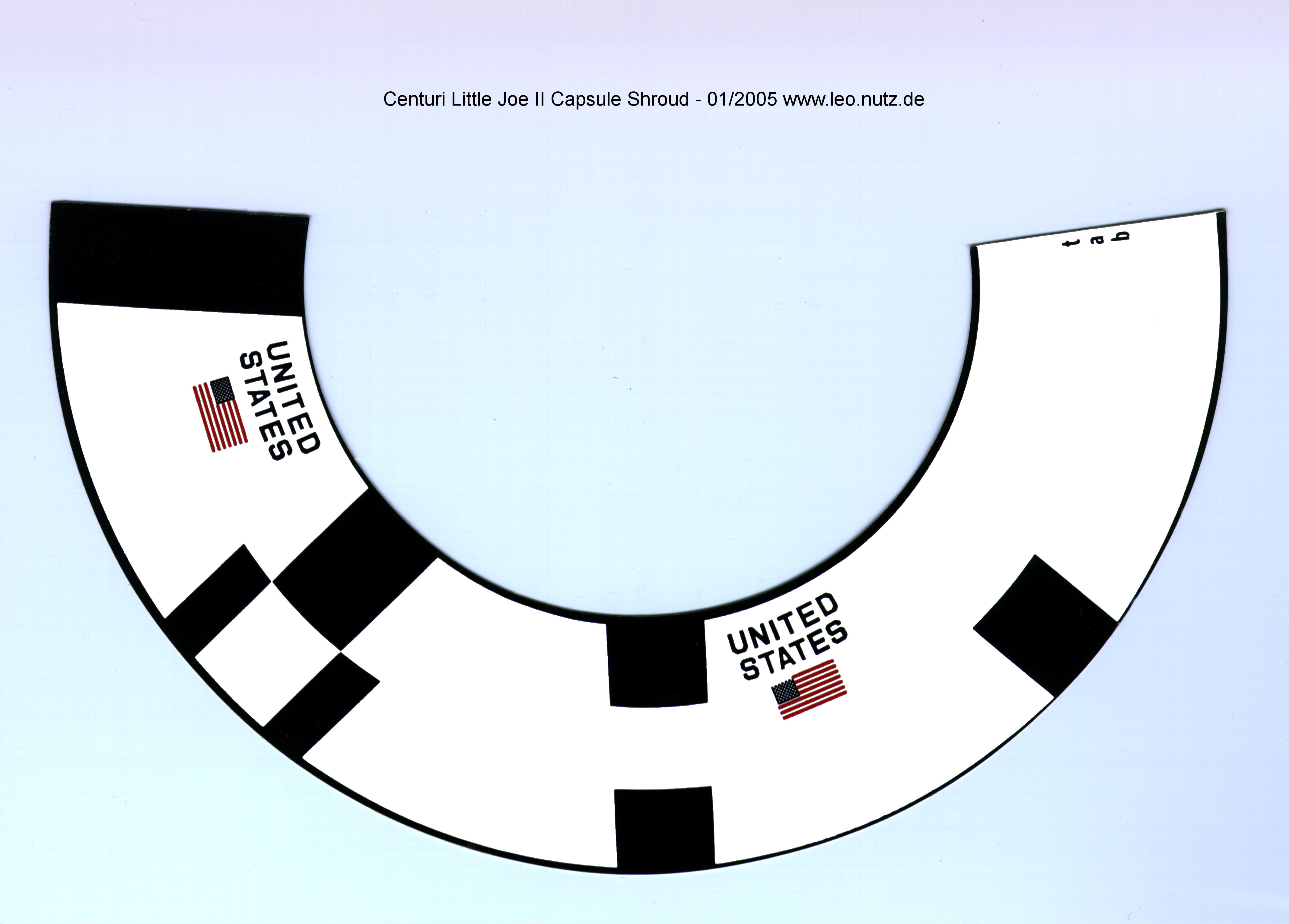
Study the drawing at the left. If tied this way the capsule will fall shoulder base first. I'd recommend upgrading the model this better, no tower break recovery.
There is a snap swivel clipped onto the low end of the tower. There is no chance of snap-back. The capsule and tower are ejected forward away from the body with much less shock.

The 1/8" elastic (on the left) ends up at about 7" long. Cotton embroidery thread (4" or so) is tied to the snap swivel and clipped to the tower.


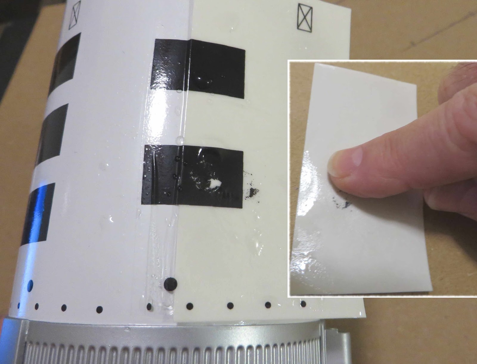
The shock cord tie down was slid into place and the liquid glue brushed on the joint afterward.


The tower has already been glued into the command module. Here I haven't glued the escape nozzles and tube on yet.
Some strong cotton embroidery string was tied to a snap swivel and clipped to the low end of the tower. TIP: #10 Cotton embroidery string is also great for parachute shroud lines - VERY strong.


At the 7" mark from the base of the C.M., tie an overhand knot around the tower string. This allows you to slip the string through the knot and get the correct ascent angle.

The cotton string is then tied around the shock cord knot and secured with a very small drop of white glue. NEVER use CA glue (super glue) to secure a knot.

On the left is the angle I ended up with. It's not exactly the 7" and 4" lengths, but pretty close.

After all was tied up, the clay loaded tower jettison motor assembly was glued to the top of the tower.

The string (under my thumb in the picture) slides in between the capsule shoulder and body tube when packed for flight. Un-clip the snap swivel from the tower when the model is on display.

Monday, July 10, 2017

Estes Apollo Little Joe II Build, Part 36, Escape Tower Decals


The vertical black bars are centered above the nozzles.
I drew a vertical pencil line to center the first bar.

You'll have to cut very close to the bottom box as it butts up against the lip of the cap.
GOTCHA: These decals are thin! I am not going to place the HUGE wrap decal on the body in one piece.

Rub some water on the tube so the decal won't freeze up in the wrong position. A little water "lube" allows movement and makes it easier to remove air bubbles.

TIP: Keep the backing on as you smooth out the first 1/4 of the decal on the tube before sliding the back over to expose and place the next quarter decal. I use a wet Q-tip to roll out water and air working from the center out to the edges.
Smooth as you go removing bubbles before sliding the backing off the next quarter area.
After you set down the first two quarter panels go back and check to be sure the first panel is straight.


Here's the finished assembly - WHEW!

Saturday, July 8, 2017

Estes Apollo Little Joe II Build, Part 35, Command Module Decals


The dashed black cut lines are too close to some of the decals. Look at the upper right single black box.

The clear coat is thin! My kit decals took only a 15 second soak to loosen up from the backing paper.

There are four 90 degree drawings for decal placement.
As you go to the right each drawing represents a quarter turn to the left. What? 

If you are looking down from the top each drawing is a quarter turn clockwise. I had to double check everything with Peter Alway's book, Rockets Of The World.

There is another drawing that doesn't agree with the the four drawings at the bottom of the page.
On the left, the UNITED STATES decal is in the wrong place. Go by the four quarter turn drawings at the bottom of the page.
The "half box" decals are also different sizes.
Here's my command module viewed from the top.
On one side of the module are four raised lines. Those are left over from the Centuri kit. You can use those to set down the first decal. The other three are centered between the tower post holes.

I centered the two UNITED STATES decals on opposite sides. The instruction drawings don't show that. If place like the quarter drawings show the UNITED STATES decals would end up at the 12 and 9 o'clock positions.I hope this is correct.

GOTCHA: According to James Duffy's build on TRF: "The "UNITED STATES" markings will not be used on this model, as the kit represents the Boost Protective Cover (BPC) and not the underlying Command Module, where the (United States) markings did appear. I'll throw them into a box of spares, as you never know when they might come in handy."
That explains why you don't see the UNITED STATES decals on the George Gassaway drawings.

EDIT: After I placed the decals I found this in the old Centuri Little Joe instructions from oldrocketplans.com - CLICK HERE


I guess I got it right. Except - the Centuri wrap has the UNITED STATES decals set to the top, not close to the bottom as shown in the Estes kit. They are on opposite sides of the command module.

Estes Apollo Little Joe II Build, Part 34, Launch Lug Gluing Tip


The back side of the two plastic launch lugs have slightly raised numbers, 1, 2, 3 and 4. (I have two kits, one kit had 1 and 3, the other had 2 and 4 on the back of the lug wall.)

The back is curved to match the body tube curve so I sanded down the numbers with 400 grit around a 24mm engine casing. This is a moot point but you do want a good glue joint on the launch lugs.

GOTCHA: The instructions show the lower lug raised from the back end of the body. Half of the lug would be over the corrugations.

TIPS: I glued my lower lug on the flat area beneath the corrugations for a better glue bond. This moves the low lug down about 1/4". This won't effect movement off the rod.
You could use a 3/16" rod through the lugs for alignment, but a 3/16 rod could be heavy and hard to work with.

I used a 1/8" aluminum rod taped to the side of the lug.
Glue the lower lug in place and let it dry. Tape the 1/8" launch rod next to the lug then glue on the upper lug. You can tuck the flat lug base under the launch rod as it dries.

Friday, July 7, 2017

Estes Apollo Little Joe II Build, Part 33, Escape Tower Nose Weight


The escape tower get 3 1/2 pats of clay weight.
They total .87 oz.
TIP: Instead of rolling the clay into small worms, cut the 1/2 pat of clay into small pieces and roll them into little balls. These will go in first into the nose cone already glued into the tube.
Drop the clay balls in a few at a time and press in place with a dowel. The clay balls pack in tighter and you aren't chasing a clay snake around the end of a body tube.

The other three pats are rolled into cylinders and pressed in with a dowel. Drop and seat the clay cylinders one at a time.


The 3 1/2 pats of clay totally fill the nose cone and tube.

GOTCHA: I glued the nozzle "hat" assembly in place with epoxy.
The only problem was the nozzle hat was airtight in the tube! Air pressure inside wouldn't allow me to seat the base of the nozzle hat against the edge of the tube.
It took a few minutes of turning the nozzle assembly to work the remaining air out of the unit. I checked back a few minutes later only to find it was being pushed out again.
Check, press and re-seat - repeat until the epoxy dries.

Thursday, July 6, 2017

Estes Apollo Little Joe II Build, Part 32, Command Module Nose Weight


I've never seen this much nose weight in a kit before -

The command module gets 2 1/2 clay weights. The total weight for me was .61 oz.
For a better, tighter fit of the clay, just don't press it into the tip of the nose.
Preform the first 1/2 pat of clay into a cone shape. Once it is pressed into place form the second clay pat into a round doughnut. Press that in on top of the first.
The third pat goes on top of that.


Flatten out and even up the clay with the back end of a hobby knife or flat end dowel.

You want the clay to adhere well without any air gaps so it won't come loose.